
Line filter

A filter and linear technology, applied in transformers, inductors, fixed inductors, etc., can solve problems such as poor elimination characteristics and inability to attenuate

Inactive Publication Date: 2002-07-10
PANASONIC CORP
View PDF0 Cites 5 Cited by
  • Summary
  • Abstract
  • Description
  • Claims
  • Application Information

AI Technical Summary

Problems solved by technology

So there will be a problem of poor cancellation characteristics for the common mode noise 36 because it cannot attenuate the wide frequency band from the low frequency region to the high frequency region

Method used


Image

  • Line filter
  • Line filter
  • Line filter

Examples


Embodiment Construction

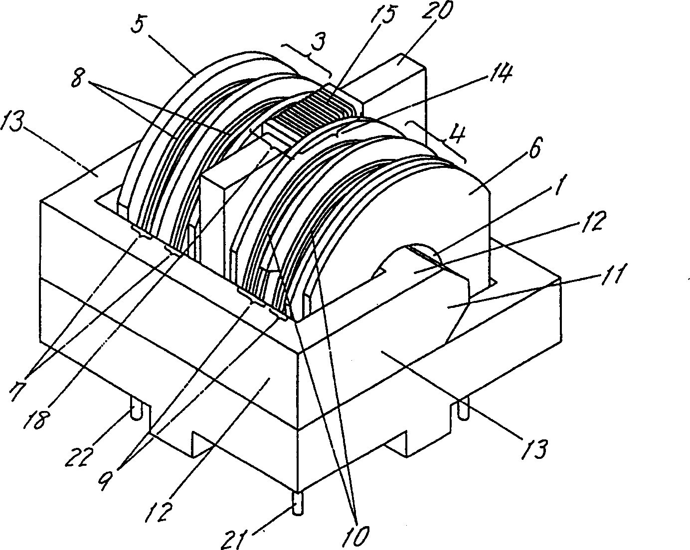
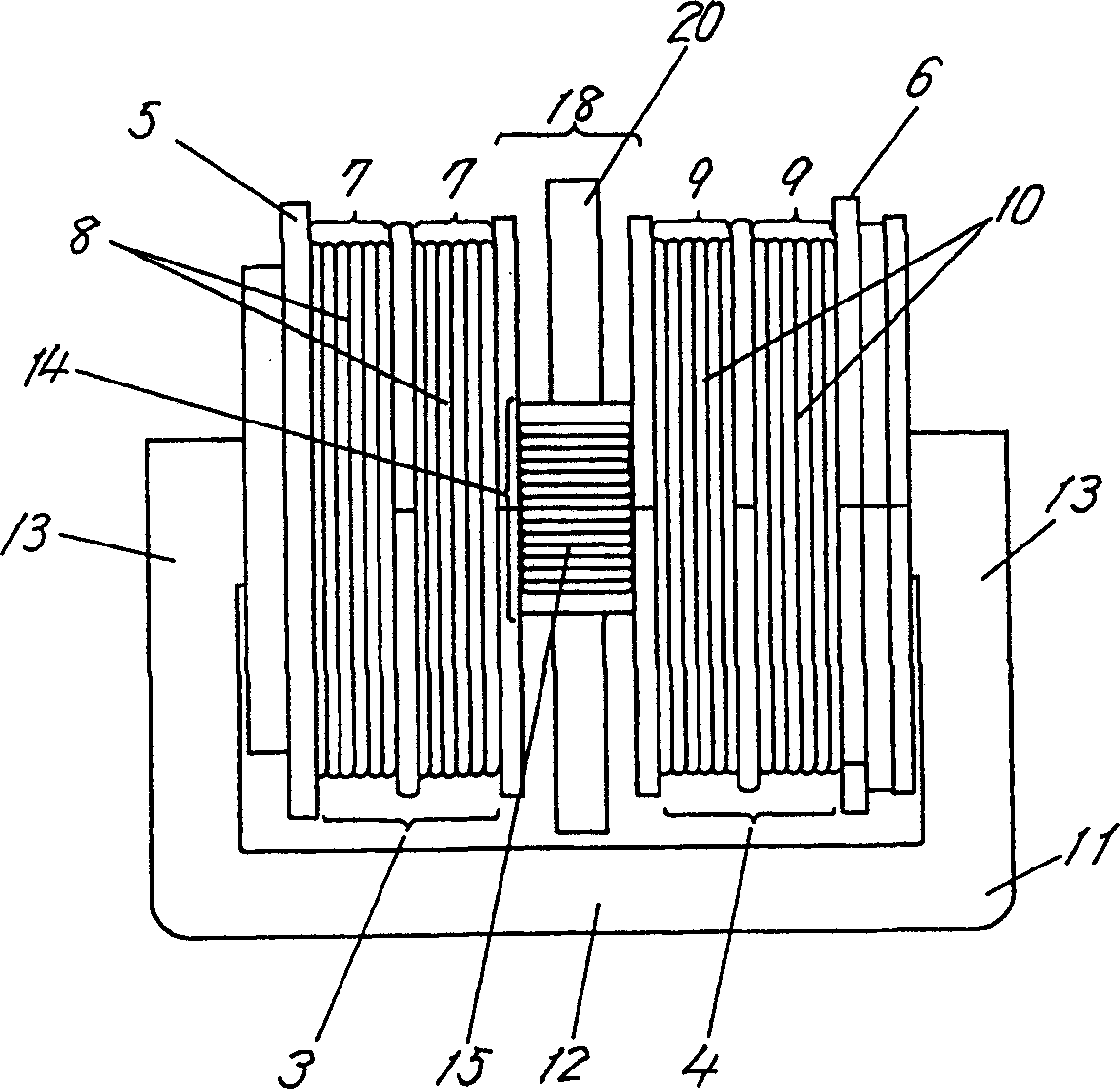
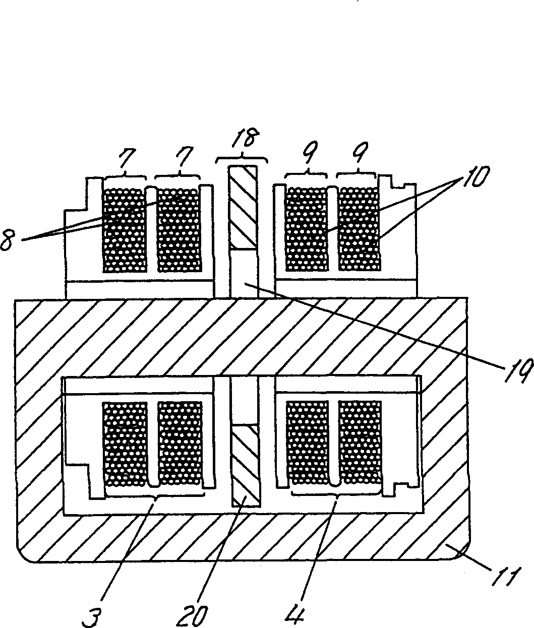
[0076] A linear filter as described in claim 1 of this specification, which includes a first bobbin and a second bobbin, each bobbin having a through hole and a coil slot for winding the coil in its axial direction, The first coil is wound on the coil slot of the first bobbin to form the first coil unit, the second coil is wound on the coil slot of the second bobbin to form the second coil unit, and the closed-loop magnetic core with the magnetic frame bar is inserted into the first coil In the through holes of the first bobbin and the second bobbin, and a first noise suppression device for eliminating common mode noise.

[0077] The first noise suppressing means comprises a first noise suppressor for the first frequency band for eliminating common mode noise in the first frequency band and another first noise suppressor for the second frequency band for eliminating common mode noise in the second frequency band a noise suppressor.

[0078] The first noise suppressor for the ...


PUM


Abstract

The present invention is intended to provide a line filter having an outstanding attenuation characteristic over a wide frequency band from low frequency band to high frequency band, with an improved elimination characteristic for common mode noises. To achieve this object, the invention incorporates a structure wherein a first coil unit (14) for second band and a second coil unit (16) for second band are disposed vertically to a closed-loop magnetic core (11).

Description

(1) Technical field [0001] This invention relates to a linear filter which is used in a variety of consumer products, among others. (2) Background technology [0002] A conventional linear filter will be described with reference to the figures hereinafter. [0003] exist Figure 55 with Figure 56 Among them, the conventional linear filter is equipped with a bobbin 32 with a through hole, the first coil 33 and the second coil 34 are wound on the bobbin 32 , and the closed-loop magnetic core 35 is inserted in the through hole of the bobbin 32 . [0004] The noise suppression device is thus constructed to eliminate common mode noise such as Figure 57 , 58 shown. This noise suppression device eliminates noise generated when the first coil 33 and the second coil 34 respectively pass through the closed-loop magnetic core 35 to obtain the same magnetic flux A and magnetic flux B in the same direction, and these two kinds of magnetic fluxes are different from each other. Offs...

Claims


Application Information

Patent Timeline
Patent Type & Authority Applications(China)
IPC IPC(8): H01F37/00
CPCH01F37/00H01F38/00
Inventor 富田浩史小田俊则石川広高森龍哉
Owner PANASONIC CORP
Learn More