
Vehicle suspension damping active adjustable hydraulic vibration reducer

A technology of hydraulic shock absorber and vehicle suspension, which is applied in the direction of liquid shock absorber, suspension, elastic suspension, etc. Simplicity, reliability and performance assurance, low-demanding effects

Inactive Publication Date: 2002-09-04
ZHEJIANG UNIV
View PDF0 Cites 37 Cited by
  • Summary
  • Abstract
  • Description
  • Claims
  • Application Information

AI Technical Summary

Problems solved by technology

However, these technologies cannot be solved well at the present stage.
The application of many sensors, high-end actuators and high-performance processors will inevitably increase the cost of the entire system, and the reliability and performance of the entire system cannot be well guaranteed

Method used


Image

  • Vehicle suspension damping active adjustable hydraulic vibration reducer
  • Vehicle suspension damping active adjustable hydraulic vibration reducer

Examples


Embodiment Construction

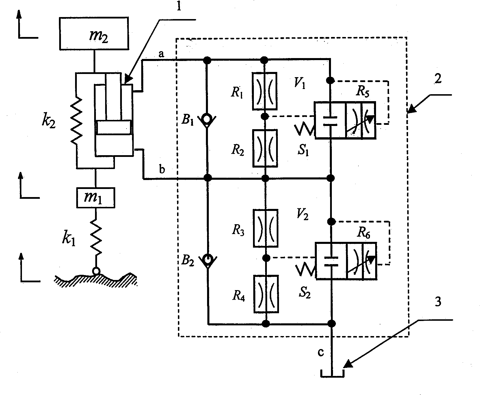
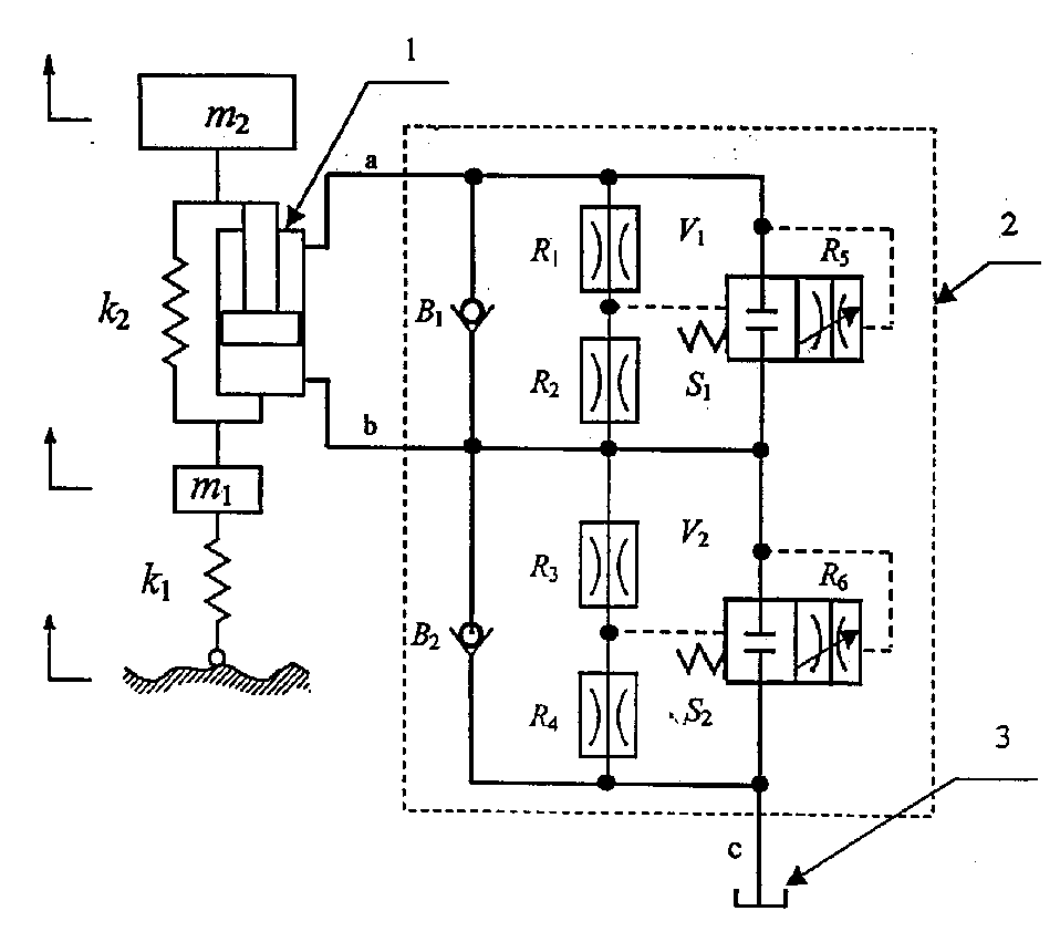
[0012] Such as figure 1 As shown, the vehicle suspension damping actively adjustable hydraulic shock absorber of the present invention includes two regulating valves V 1 , V 2 The hydraulic adjustable damping control valve 2 is composed of a damping cylinder 1 and an oil storage tank 3 connected with the hydraulic adjustable damping control valve 2; the upper chamber of the damping cylinder 1 is connected to the first regulating valve V through the first oil passage a 1 check valve B 1 One end of the two fixed orifice dampers in series R 1 , R 2 One end of the variable orifice damper R 5 One end is connected; the lower chamber of the damping cylinder 1 is connected to the first regulating valve V through the second oil passage b 1 check valve B 1 The other end of the two fixed orifice dampers in series R 1 , R 2 The other end of the variable orifice damper R 5 The other end of the damping cylinder 1 is connected to the other end, and the lower chamber of the damping c...


PUM


Abstract

The hydraulic vibration damper includes hydraulic adjustable damping control valve formed from two regulating values and vibration-damping cylinder connected with the above damping control valve and fuel tank. It is a pure mechanical hydraulic damping network structure, adopts dynamic pressure feedback characteristics, can be adapted to variour road conditions and influence of time-varying factorof suspension oneself so as to implement damping active regulation. It directly utilizes the information of internal hydraulic pressure of vibration-damping cylinder to reflect road condition and vibration condition of vehicle, so that it has no need of other various sensors to make signal conversion.

Description

technical field [0001] The invention relates to a device combined with a spring and a shock absorber, in particular to an actively adjustable hydraulic shock absorber for vehicle suspension damping. Background technique [0002] The concept of semi-active suspension was proposed by Crosby et al. in the 1970s, and its mass production application began in the early 1980s, when the first generation of variable damping shock absorbers were introduced, but its improvement in suspension performance was Very limited; in the early 1990s, F.H.Besinger, R.Rajamary, Robin and others also conducted their own research on semi-active suspensions, and made a lot of experiments; in recent years, semi-active suspensions and their active damping can be adjusted Shock absorbers have been developed into corresponding products. [0003] In general, semi-active suspensions are still far from being accepted by the industry. One of the reasons is the lack of a truly reliab...

Claims


Application Information

Patent Timeline
Patent Type & Authority Applications(China)
IPC IPC(8): B60G15/00B60G17/06F16F9/14
Inventor 王庆丰涂华刚
Owner ZHEJIANG UNIV
Learn More