Laser cutting-welding technology and apparatus for sheet

A laser cutting and combined process technology, applied in laser welding equipment, welding equipment, metal processing equipment, etc., to achieve the effects of compact equipment, reduced cost, and avoidance of optical path switching errors

Inactive Publication Date: 2002-09-11
HUAZHONG UNIV OF SCI & TECH
View PDF0 Cites 35 Cited by
  • Summary
  • Abstract
  • Description
  • Claims
  • Application Information

AI Technical Summary

Problems solved by technology

[0003] The invention proposes a thin plate laser cutting-welding combination process and its equipment, which are used to solve the problem of high-precision non-deformation laser tailor welding of large-format metal thin plates

Method used


Image

  • Laser cutting-welding technology and apparatus for sheet
  • Laser cutting-welding technology and apparatus for sheet
  • Laser cutting-welding technology and apparatus for sheet

Examples


Embodiment Construction

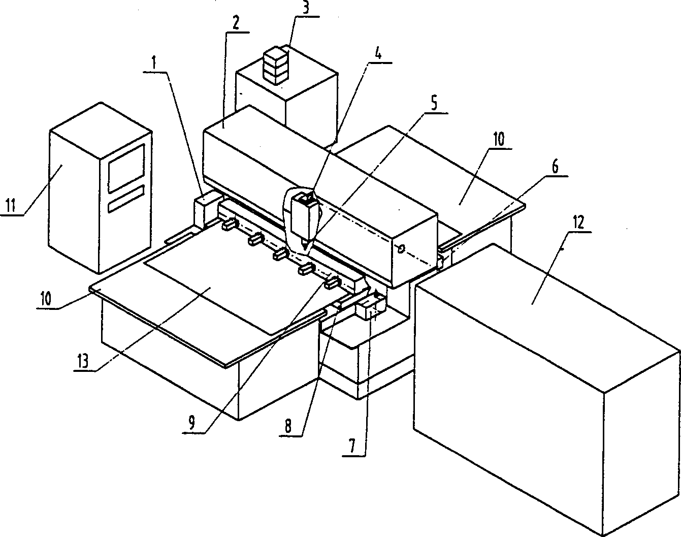
[0021] The specific implementation manners of the present invention are explained below in conjunction with the accompanying drawings. figure 1 The equipment shown is composed of blank plate positioning mechanism 1, Y axis 2, hydraulic system 3, light guide system 4, cutting-welding focusing head 5, cutting and welding conversion mechanism 7, right jaw 6, left jaw 8, blank plate Clamping mechanism 9, auxiliary rack 10, numerical control system 11 and laser 12 are formed, and 13 is blank plate.

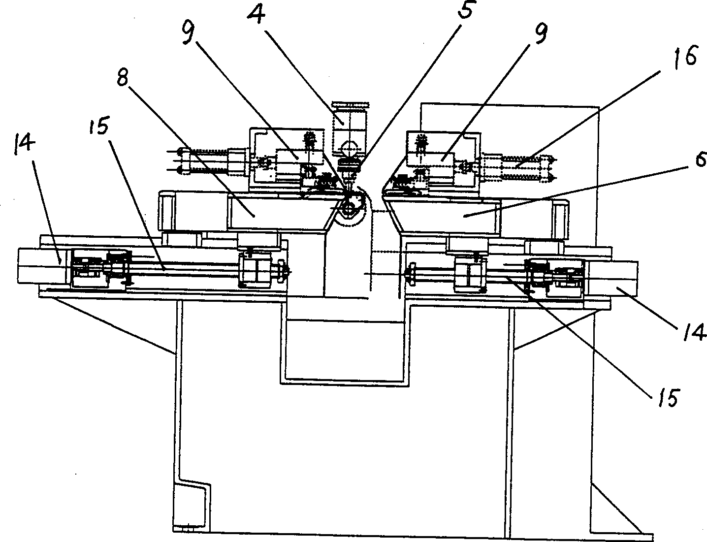
[0022] figure 2 Further describe the centering and splicing mechanism of the blank plate of the present invention, which is composed of a right jaw 6 and a left jaw 8, which are respectively driven by a stepping motor 14 and a ball screw 15, and right and left blank plate clamps are respectively placed on the right and left jaws. The tightening mechanism 9 is driven by a hydraulic cylinder 16.

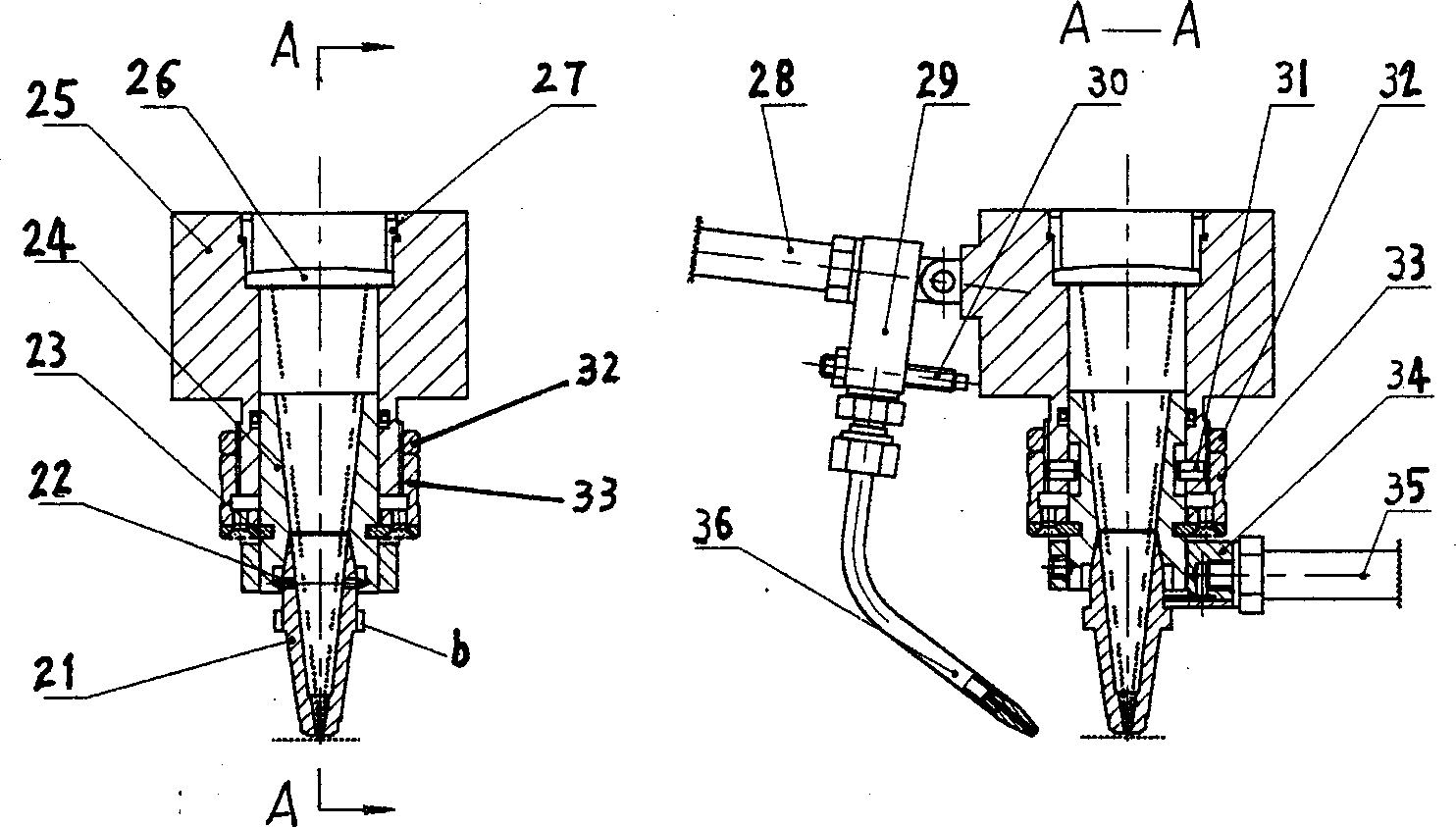
[0023] image 3 Indicate the detailed structure of the cutting-welding focusing head 5:...


PUM


Abstract

A laser cutting-welding technology for large-area metallic sheet includes such steps as cutting the edges of two metallic sheets to be welded by a laser head, splicing them together while automatically compensating the size loss of cut seam, and welding along the spliced seam by the same laser head. Its apparatus is composed of Y axle, laser head, light guide system, laser device, auxiliary supporter, digital control system, blank sheet, locator, and splicing mechanism. Its advantages include compact structure, high laser utilization rate, high accuracy and no deformation.

Description

technical field [0001] The invention belongs to the laser processing technology, in particular to a process and equipment for cutting and welding metal plates by using a laser. Background technique [0002] Laser tailor welding of metal blanks has the characteristics of high welding speed, no deformation, narrow weld seam, good joint performance and easy automation. Major automobile manufacturers in the world use laser tailor welding to form various covering parts of cars in the manufacture of car bodies. The blank plate is then stamped and formed as a whole to optimize materials, reduce weight, and simplify the stamping process, thereby reducing costs. However, due to the small heating spot of laser welding and no welding wire to add metal to fill the gap, the straightness of the edge of the plate to be joined and the quality of the end face are extremely high to ensure that the gap between the butt plates is extremely small, otherwise the quality of the joint cannot be gua...

Claims


Application Information

Patent Timeline
IPC IPC(8): B23K26/02B23K26/12B23K26/24B23K26/38B23K26/70
Inventor 胡伦骥汤漾平刘建华龚时华王春明朱国力段正澄
Owner HUAZHONG UNIV OF SCI & TECH
Why Eureka
Try Eureka