
Plant uproot device

A plant-integrated technology, applied in the fields of botanical equipment and methods, cutting tools, cutting equipment, etc., can solve the problems of increasing the diameter and wall thickness of the drive shaft, the drive shaft cannot achieve durability, and the complex structure.

Inactive Publication Date: 2002-10-02
HONDA MOTOR CO LTD
View PDF1 Cites 15 Cited by
  • Summary
  • Abstract
  • Description
  • Claims
  • Application Information

AI Technical Summary

Problems solved by technology

However, if the transmission shaft thus manufactured (i.e., a tube made of fiber-reinforced resin) is required to have the same rigidity as steel, it is inevitable to increase the diameter and wall thickness of the transmission shaft
This is not feasible since increasing the diameter of the drive shaft would require increasing the diameter of the operating rod through which the drive shaft passes
In addition, fixing the metal joint to the tubular propeller shaft made of reinforced fiber resin in the above-mentioned manner brings about a complicated structure
In addition, at and around the end of the resin propeller shaft to which the metal joint is fixed, the propeller shaft cannot achieve sufficient durability

Method used


Image

  • Plant uproot device
  • Plant uproot device
  • Plant uproot device

Examples


Embodiment Construction

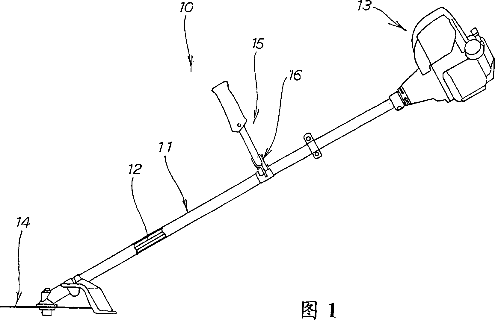
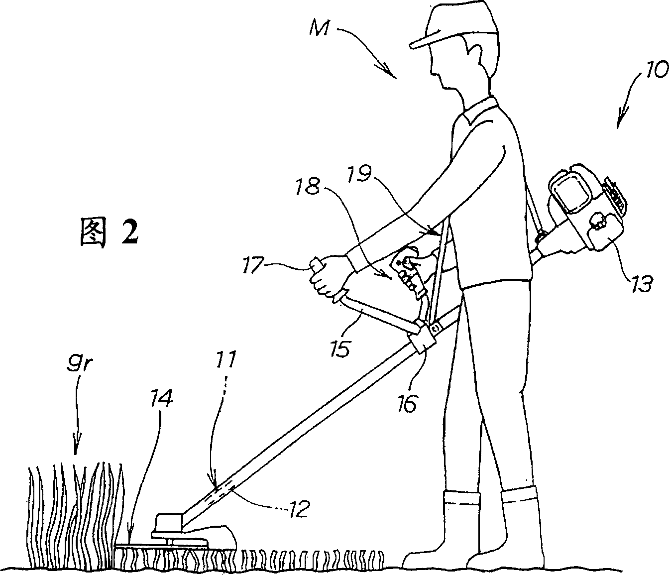
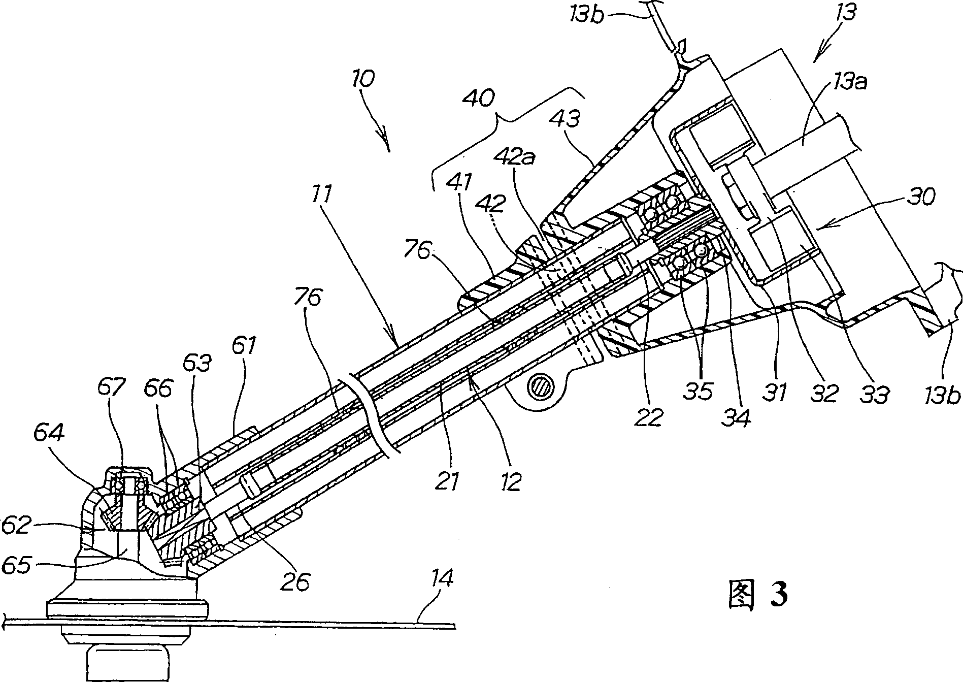
[0020] Figures 1 and 2 show a vegetation removal device 10 according to the invention which can be used to remove unwanted vegetation such as shrubs, weeds or grasses. The plant removal device 10 comprises: a tubular operating rod 11, a driving force transmission shaft or a drive shaft 12 passing through the operating rod 11, a prime mover or a driving source device 13 installed at one end of the operating rod 11, such as a motor or an electric motor, And the cutting blade 14 installed on the other end of the operating rod 11. The drive shaft 12 can be rotated by actuating the drive source device 13 , and therefore, the cutting blade 14 can be rotated by the drive source device 13 through the drive shaft 12 . The plant removal device 10 also includes a U-shaped handle 15 fixed at a substantially middle position in the longitudinal direction of the operating rod 11 . Specifically, the handle 15 is fixed to the operating rod 11 via a handle frame 16 and has left and right handl...


PUM

PropertyMeasurementUnit
lengthaaaaaaaaaa

Abstract

A plant eradication device, the driving shaft (12) of which comprises a slender shaft main part (21) made of titanium alloy, and a shaft end made of steel and integrally connected with the opposite end of the shaft main part (21) part (22,26). Titanium alloys have substantially the same mechanical strength as steel. Therefore, the shaft main part (21) made of titanium alloy can ensure the rigidity required by the general plant removal machine, and can reduce the weight of the drive shaft, thereby reducing the undesired droop-induced vibration caused by the self-weight of the shaft .

Description

technical field [0001] The present invention relates generally to a vegetation removal device for removing unwanted vegetation such as shrubs, weeds or grasses, and in particular to an improved drive shaft for use in a vegetation removal device which can drive a prime mover or The driving force of a source device such as a motor or an electric motor is transmitted to the cutting blade. Background technique [0002] In general, weeds that grow on paths between paddy fields and the like are likely to be breeding grounds for pests, so these weeds must be eradicated several times a year. Since the work of eradicating weeds is usually very heavy, so far there have been multiple automatic weed eradicating machines and put into practical use. Among them, the shoulder-mounted weed remover is very popular due to its small size and easy operation. In most of the shoulder-mounted weed cutters, the drive shaft or driving power transmission shaft passing through the operating rod is dr...

Claims


Application Information

Patent Timeline
Patent Type & Authority Applications(China)
IPC IPC(8): A01D34/76A01D34/68A01D34/90
CPCA01D34/90A01D34/68
Inventor 藁科诚内谷博明佐佐木英志
Owner HONDA MOTOR CO LTD
Learn More