
Method for production of electric energy and MHD generator therefor

A technology of magnetohydrodynamics and generators, applied in the field of power engineering, can solve problems such as not meeting ecological safety requirements, complex stability, and low device efficiency

Inactive Publication Date: 2002-10-09
奥利佛·威亚斯拉夫维奇·格瑞斯凯维奇 +3
View PDF0 Cites 2 Cited by
  • Summary
  • Abstract
  • Description
  • Claims
  • Application Information

AI Technical Summary

Problems solved by technology

This known method and device is inefficient, rather complicated and has low stability
Furthermore, this known method does not meet ecologically safe requirements

Method used


Image

  • Method for production of electric energy and MHD generator therefor
  • Method for production of electric energy and MHD generator therefor
  • Method for production of electric energy and MHD generator therefor

Examples


Embodiment Construction

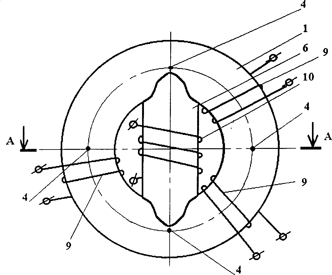
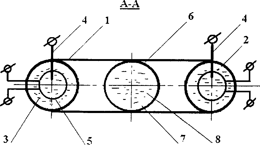
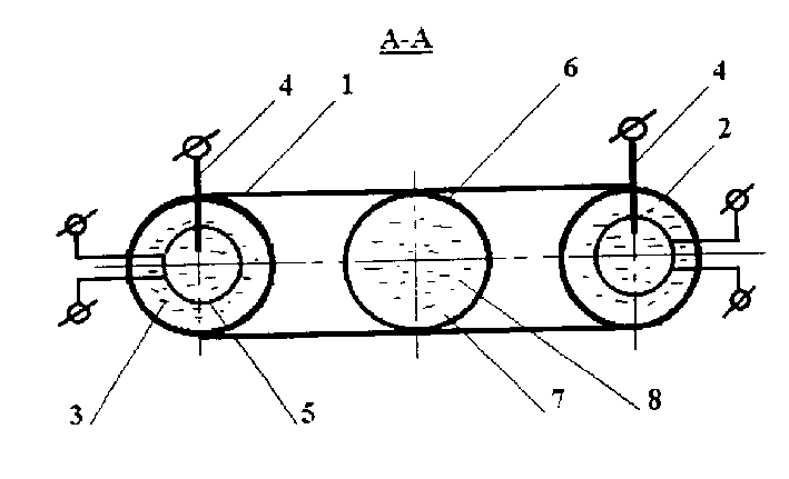
[0019] The invention is illustrated by the example of Gritskevich's generator.

[0020] The magnetohydrodynamic generator comprises a hollow, sealed annular cermet body 1 whose inner surface is covered with a coating 2 having a synergistic effect, and a cavity filled with distilled water 3 added with weighted water. In the channel of the main body 1, there are electrodes 4 made of hard alloy material connected to the capacitor bank, and field windings 5 ​​connected to the power supply. Inside the ring of the main body 1, there is a composite cylindrical stabilization chamber 6 made of cermet, which communicates with the channel of the main body 1. The inner surface of the chamber 6 is also covered with a synergistic coating 7 and the cavity is filled with distilled water 8 added with heavy water. The main body 1 and the chamber 6 have power windings 9 and 10 on their exterior.

[0021] The magnetohydrodynamic generator operates in the following way: the water 3 which has bee...


PUM


Abstract

The purpose of the present invention is to increase the output, reliability, environmental safety and to simplify the design of a magnetohydrodynamic generator. The energy generation method of the present invention includes the following steps: making the polar liquid (8) move in a predetermined direction along the completely sealed channel (1), circulate through a moving magnetic field, and collect the generated electric energy with an electromagnetic coil. The polar liquid is ionized, at least initially, for example by means of electrodes (4). The inner wall (2) of the channel has a dielectric constant higher than that of the liquid.

Description

technical field [0001] The invention relates to power engineering, ie to the generation of electrical energy by means of magnetohydrodynamic generators. Background of the invention [0002] The generation of energy, in particular heat, by arranging water to move in a predetermined direction in a closed loop is a well known method (WO90 / 00526, 1990). This approach exploits the unique properties of water to limit the release of energy due to the breaking of water's hydrogen bonds. In addition, the release of electrical energy accompanying thermal energy is also noticeable. However, this method does not produce usable electrical power. A similar approach using not only water but also any polar liquid (RU2124681, 1999) justifies releasing the additional energy of the liquid, ie at the expense of the efficiency of the cold fusion reaction and cavitation process methods. This method is also unsuitable for generating electrical energy. [0003] There is a method and device (SU ...

Claims


Application Information

Patent Timeline
Patent Type & Authority Applications(China)
IPC IPC(8): G01Q60/22H02K44/08H02K44/12H02K44/14H02K44/16
CPCH02K44/085H02K44/08
Inventor 奥利佛·威亚斯拉夫维奇·格瑞斯凯维奇鲍瑞斯·奥利佛维奇·格瑞斯凯维奇
Owner 奥利佛·威亚斯拉夫维奇·格瑞斯凯维奇
Learn More