Power filling method and apparatus

A powder filling and powder technology, applied in the field of methods and devices

Inactive Publication Date: 2002-10-23
RICOH KK
View PDF1 Cites 9 Cited by
  • Summary
  • Abstract
  • Description
  • Claims
  • Application Information

AI Technical Summary

Problems solved by technology

[0005] This prior powder filling method has another problem when applied to copiers, printers or simila

Method used


Image

  • Power filling method and apparatus
  • Power filling method and apparatus
  • Power filling method and apparatus

Examples


Embodiment Construction

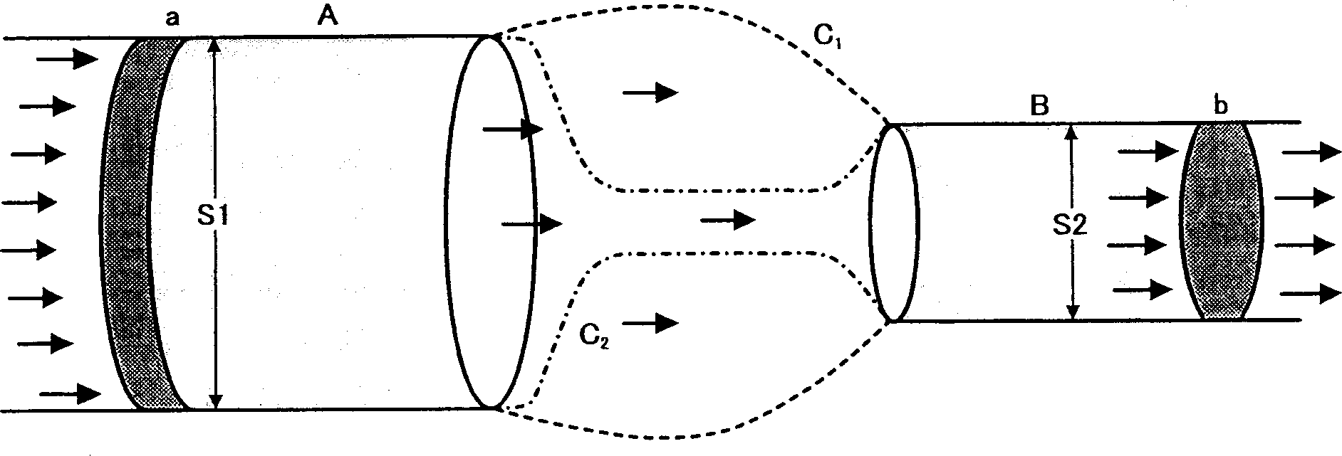
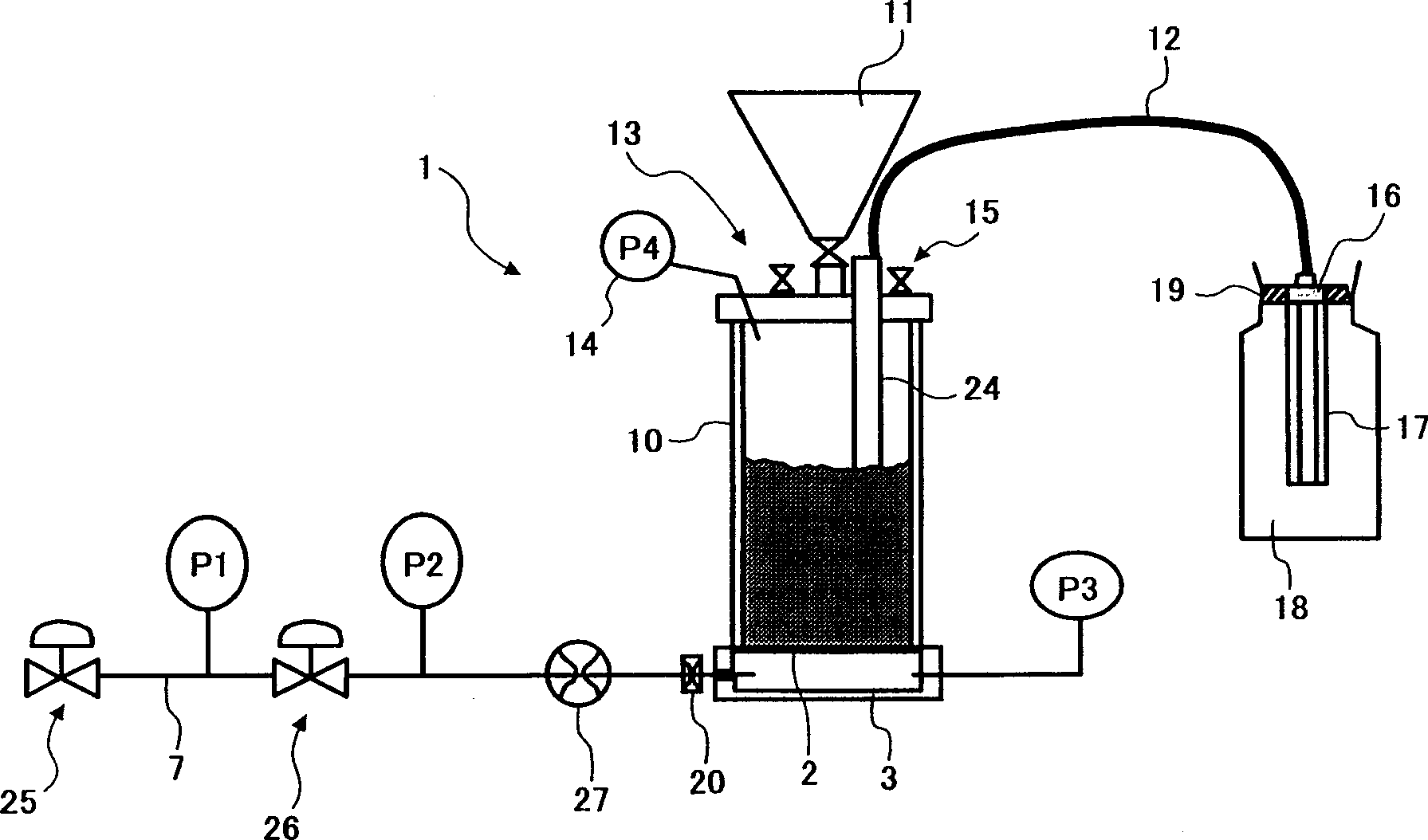
[0017] Systems that fluidize powder with gas and transport the powder pneumatically, for example through a tube, are available. However, this system has a problem when toner or the like with a particle size of 20 μm or less, especially 10 μm or less, is fluidized and filled in the toner container. In this case, the powder needs to be prevented from flying and the gas needs to be discharged from the container after filling. Although equipment that meets this requirement can be installed in a factory or similar large-scale facility, it is not suitable for ordinary offices.

[0018] Toner or similar fine powders have a very large surface area to volume ratio, and in many cases they adhere to each other, so they need to be loosened, for example, by a stirrer before use. The loose powder mainly reflects the surface condition of the block being ground to make the powder and has nothing to do with the specific gravity of the block, so Brownian motion continues. As is known from experienc...


PUM

PropertyMeasurementUnit
Volume average particle sizeaaaaaaaaaa

Abstract

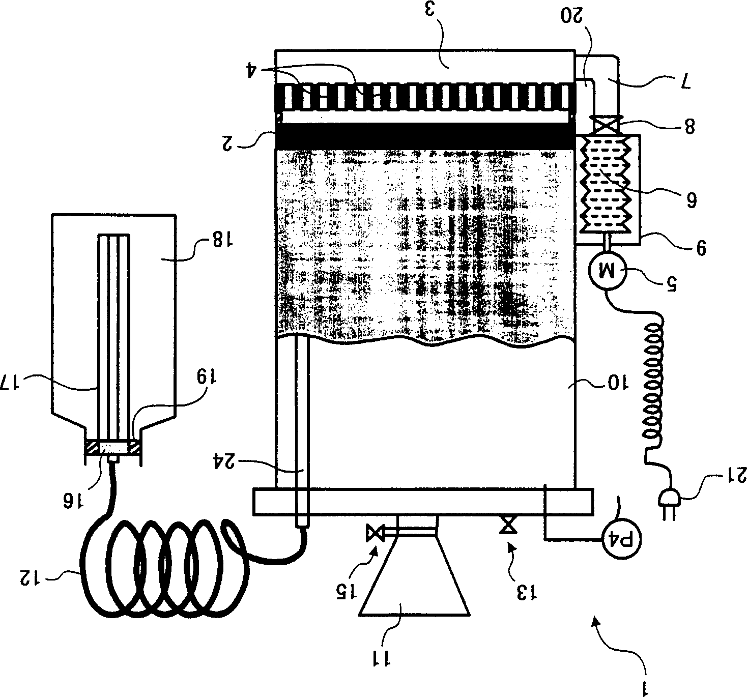
The powder filling device of the present invention can uniformly send gas into the powder, so that the powder is fluidized with a minimum amount of gas. The gas transports the fluidized powder to the bottom of containers with small ports or complex structures. Gases in the powder introduced into the container are released through the powder bed between the nozzle and the mouth. The device thus enables easy and dense packing of powder in the container without causing the powder to fly out of the container. Furthermore, the device is small, easy to carry, easy to operate, and therefore can be operated by anyone, anywhere.

Description

Technical field [0001] The present invention relates to a method for filling powder with a particle size of 20 μm or less in a container with a small mouth or a small volume, or a container that cannot rely on gravity to fill the powder, and a device thereof. More specifically, the present invention relates to a method and apparatus for directly filling toner in a toner cartridge for an image forming apparatus or a developing assembly included in the image forming apparatus. Background technique [0002] For example, a rotary valve, a screw feeder, and an auger belong to a group of components that are often used to fill powder into a container. After a container has been placed under such a filling part, the filling part works to increase the bulk density of the powder and transport the powder into the container. This type of filling scheme can efficiently fill the powder in a container with a pre-selected volume. [0003] For example, Japanese Patent Laid-Open Publication No. 9-...

Claims


Application Information

Patent Timeline
IPC IPC(8): B65G53/22
CPCB65G53/22
Inventor 牧野邦夫天野浩里
Owner RICOH KK
Why Eureka
Try Eureka