Pressure-reducing and flow rate-increasing swtich liquid pressure source with oil returning back pressure

A technology for switching hydraulic sources and back pressure, applied in fluid pressure converters, mechanical equipment, etc., can solve the problems of one-way valve pressure fluctuations, large throttling losses, energy waste, etc., achieve the best energy-saving effect, reduce dynamic loss, The effect of reducing pressure fluctuations

A technology for switching hydraulic sources and back pressure, applied in fluid pressure converters, mechanical equipment, etc., can solve the problems of one-way valve pressure fluctuations, large throttling losses, energy waste, etc., achieve the best energy-saving effect, reduce dynamic loss, The effect of reducing pressure fluctuations

CN1375640AInactive Publication Date: 2002-10-23ZHEJIANG UNIV

Image

  • Pressure-reducing and flow rate-increasing swtich liquid pressure source with oil returning back pressure
  • Pressure-reducing and flow rate-increasing swtich liquid pressure source with oil returning back pressure

Examples


Embodiment Construction

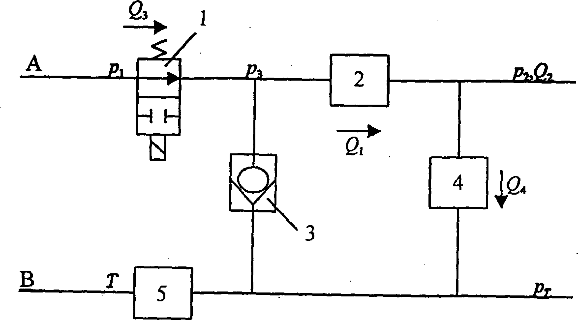
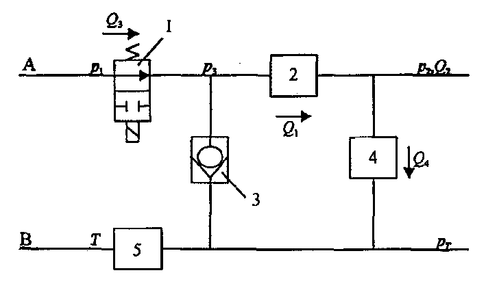
[0011] As shown in the figure, it includes a high-speed switching valve 1, a liquid sensing element 2, a one-way valve 3, a liquid capacity element 4, and a back pressure valve 5; the high-speed switching valve 1 and the liquid sensing element 2 are connected in series in the oil supply circuit of the hydraulic bus On A, the back pressure valve 5 is connected to the oil return circuit B of the hydraulic bus. The output end is connected to the output end of the high-speed switching valve 1 and the input end of the liquid sensing element 2, the input end of the liquid capacity element 4 is connected to the input end of the liquid sensing element 2, and the input end of the liquid capacity element 4 is connected to the input end of the liquid sensing element 2. The output end is connected, the output end of the one-way valve 3, the output end of the liquid capacity element 4 and the input end of the back pressure valve are connected.

[0012] p in the figure 1 Indicates the oil ...


PUM


Abstract

The present invention discloses a pressure-decreasing flow-increasing type switch hydraulic source with oil-returning backpressure, which is characterized by that the high-speed switch valve and liquid inductance element are series-connected on the hydraulic main line oil supply pipeline, the backpressure valve is connected on the hydraulic main line oil-returning pipeline, the non-return valve and liquid volume element are respectively cross-connected between the hydraulic main line oil supply pipeline and oil-returning pipeline, the output end of the non-return valve is connected with output end of high-speed switch valve and input end of liquid inductance element, and the input end of liquid volume element is connected with output end of liquid inductance element, and the output end ofnon-return valve and output end of liquid volume element are connected with input end of backpressure valve.

Description

technical field [0001] The present invention relates to boosters or liquid pressure converters. Background technique [0002] One of the biggest advantages of the hydraulic system is its multi-actuator feature, that is, a single hydraulic pump can supply oil and drive multiple actuators at the same time. [0003] At present, most of the production line hydraulic systems of industrial, mining, metallurgical, steel and other enterprises adopt the hydraulic bus oil supply mode: the pump station outputs one pressure oil pipe, one control oil, one return oil and one leakage oil, and all hydraulic actuator control units All are hung on the hydraulic bus. Since the oil supply pressure on the hydraulic bus is constant, the load of each actuator is required to adapt to the oil supply pressure, or a pressure reducing valve is required (reducing the oil supply pressure on the hydraulic bus to adapt to the actuator load ) and then hang the actuator to the h...

Claims


Application Information

Patent Timeline
23 Oct 2002
Publication
CN1375640A
IPC
F15B3/00
Inventors
顾临怡; 张晓峰