Method and apparatus for measuring light transmissivity

A technology of light transmittance and measuring equipment, applied in the direction of transmittance measurement, measuring device, testing optical performance, etc., can solve problems such as errors, adverse effects of measurement convenience, etc.

Inactive Publication Date: 2002-10-23
HOYA CORP
View PDF0 Cites 15 Cited by
  • Summary
  • Abstract
  • Description
  • Claims
  • Application Information

AI Technical Summary

Problems solved by technology

When the cross-sectional area of ​​the measuring light beam is quite large and the difference in diopter is large, the difference in the attenuation of the luminous flux cannot be ignored, resulting in errors in the measurement
[0014] Therefore, in the device for measuring the light transmittance disclosed in

Method used


Image

  • Method and apparatus for measuring light transmissivity
  • Method and apparatus for measuring light transmissivity
  • Method and apparatus for measuring light transmissivity

Examples


Embodiment Construction

[0028] A method for measuring light transmittance and an apparatus for measuring light transmittance as embodiments of the present invention will be described below with reference to the accompanying drawings.

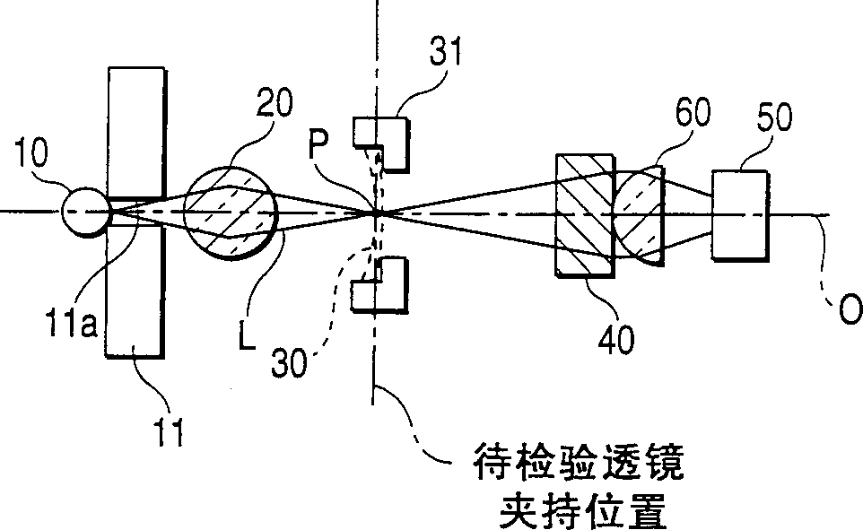
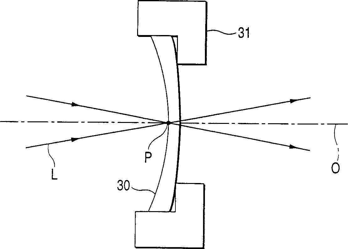
[0029] The apparatus for measuring light transmittance of the present invention includes two apparatuses for measuring light transmittance having the same optical system and different measurement wavelengths. figure 1 One of these two devices is drawn in and not the other.

[0030] exist figure 1 Among them, the light source 10, the small hole plate 11, the ball lens 20, the lens holding device 31 to be inspected, the interference filter 40, the hemispherical lens 60 and the light receiving element 50 are arranged in such a way that the optical axes are on the same optical axis O figure 1 Set in sequence from left to right.

[0031] The light source 10 emits measurement light L. As shown in FIG. A light emitter that emits light beams containing a large number of ...


PUM


Abstract

The invention relates to a method and equipment for measuring light transmittance, which can realize cheap and convenient measurement of the light transmittance of an optical lens with refractive power with excellent precision. The method for measuring light transmittance includes deriving the light transmittance of a lens to be inspected (30) from a value corresponding to a ratio when the lens to be inspected (30) is positioned at In the optical path of the measuring light (L) of the detection device (50), the intensity of the measuring light (L) detected by the light detecting device (50) when the measuring light (L) passes through the lens (30) to be inspected The ratio of the intensity of the measuring light (L) detected by the light detecting device (50) when the lens (30) is not placed in the optical path of the measuring light (L) so that the measuring light (L) does not pass through the lens (30) to be inspected, Wherein the measurement light (L) passes through the lens to be inspected (30) under the condition that the light of the measurement light (L) converges at or near the position where the lens to be inspected (30) is located.

Description

technical field [0001] The present invention relates to a method according to claim 1 for measuring the light transmittance of an optical lens, such as eyeglasses, more conveniently, and to an apparatus according to claim 3 for carrying out the method according to the invention. Background technique [0002] In optical shops, as one of various inspections on the performance of glasses, it is sometimes necessary to check the light transmittance of the glasses for ultraviolet light or visible light. [0003] As a method of measuring the light transmittance, there is known a method in which the light transmittance is accurately measured by using an integrating sphere in a photometric system so that the measured value can be measured even when the measurement light is diverged or converged by the lens to be inspected. No error occurs in . However, integrating spheres are relatively expensive, and thus it is difficult to widely popularize integrating spheres in optical shops. ...

Claims


Application Information

Patent Timeline
IPC IPC(8): G01J3/28G01B11/02G01M11/02G02B3/00G02C13/00
CPCG01M11/0285G01B11/02
Inventor 秋山久则依田寿郎
Owner HOYA CORP
Why Eureka
Try Eureka