Welding system

A welding system and interface technology, which is applied in the direction of welding power supply, welding power supply, welding equipment, etc., can solve the problems of long connecting wire length and low efficiency

Inactive Publication Date: 2002-12-11
OHARA
View PDF0 Cites 10 Cited by
  • Summary
  • Abstract
  • Description
  • Claims
  • Application Information

AI Technical Summary

Problems solved by technology

[0004] At the same time, even if the generally well-known device net shown in Fig. 2 is used as an example of a field bus communication device, there are problems such as the length of each connecting wire becoming long and the need to use a tap 33, thereby requiring a separate installation of ...

Method used


Image

  • Welding system
  • Welding system
  • Welding system

Examples


Embodiment Construction

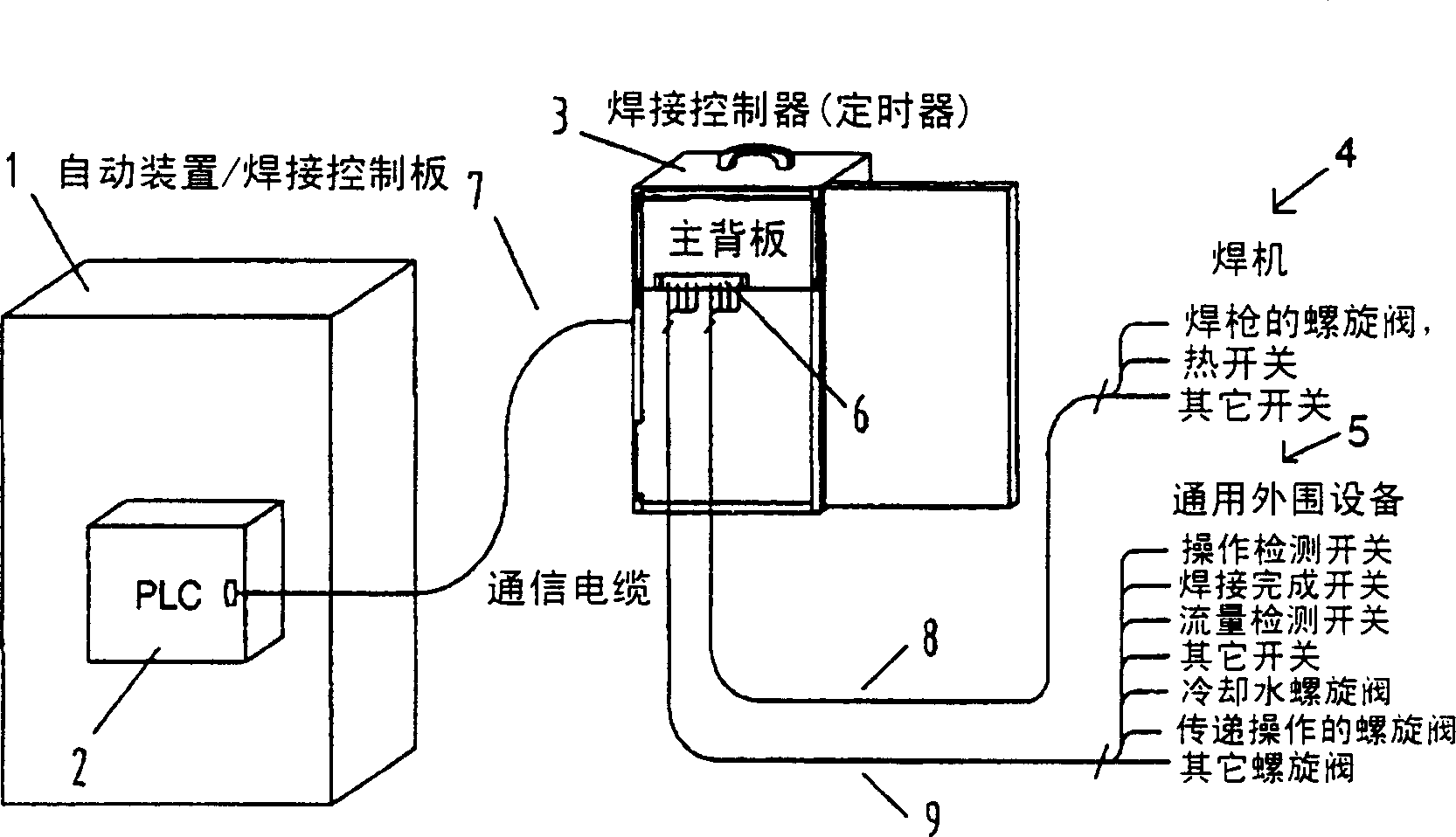
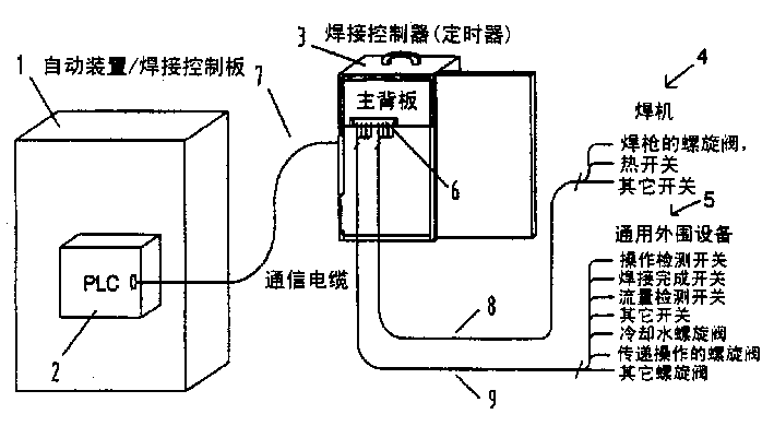
[0011] A welding controller according to a preferred embodiment of the present invention will be described below with reference to the accompanying drawings. figure 1 is a schematic diagram showing the configuration of an FA system suitable for operating the welding controller of the present invention.

[0012] exist figure 1 Among them, 1 represents the automatic device / welding control board, and 2 represents the PLC placed on the automatic device / welding control board 1. 3 indicates a timer used as a welding controller, 4 indicates a welding machine to be controlled by the welding controller 3, 5 is a general peripheral device placed on the periphery of the welding machine 4, and correctly represents such as a screw valve for controlling cooling water, a flow detection switch Peripheral equipment such as a screw valve for transmitting operation, a switch for inputting operation detection information, etc.

[0013] Between the PLC2 and the I / O interface (terminal block) 6 o...


PUM


Abstract

A welding system that can shorten the length of connecting wires and make efficient use of equipment as a whole. The system comprises: a welding controller (3) equipped with an I/O interface (6); equipped with a programmable logic controller (2) and connected to the welding controller (3) through a field bus interface (7) as a communication device ) on the I/O interface (6) of the controller (1); the welding machine (4) and general peripheral equipment (5), wherein the welding controller (3) communicates from the programmable logic controller through the field bus interface (7) (2) Receive instructions to control the welding machine (4) and general peripheral equipment (5).

Description

technical field [0001] The invention relates to a welding system including a welding controller. Through a network, the welding controller can operate according to instructions issued by a controller equipped with a PLC (Programmable Logic controller). Background technique [0002] Generally, welding machines and general Peripherals are controlled by arranging multi-strand wires, that is, by connection of multi-strand wires used between controllers equipped with PLCs and the like and welding controllers, general-purpose peripherals. In this case, since the device needs to be connected by multi-strand wires to output control commands, it is very complicated in terms of information or command transmission and the composition of the command device. [0003] Therefore, it is considered to use the well-known field bus as a communication device to realize the command transmission from the controller equipped with PLC to the welding controller and general peripheral equipment (gen...

Claims


Application Information

Patent Timeline
IPC IPC(8): B23K37/00B23K9/095B23K9/10B23K9/12B23K11/24B23K11/25G05B19/05H02M9/00
CPCB23K9/0953B23K9/0956B23K9/1056B23K11/241B23K11/252B23K37/00
Inventor 樋口大祐小原保宏佐藤善宏
Owner OHARA
Why Eureka
Try Eureka