Loudspeaker and mobile terminal equipment

A mobile terminal and loudspeaker technology, applied in the direction of loudspeaker transducer fixation, sub-office equipment, sensors, etc., can solve the problems of increased diameter, insufficient magnetic energy, and inability to obtain sound pressure, etc., and achieve high degree of freedom, high drive efficiency, and good Effects of drive characteristics and acoustic characteristics

Inactive Publication Date: 2002-12-11
PANASONIC CORP
View PDF3 Cites 15 Cited by
  • Summary
  • Abstract
  • Description
  • Claims
  • Application Information

AI Technical Summary

Problems solved by technology

The simple reduction of the diaphragm or the magnetic circuit according to the reduction of the speaker space, for example, leads to the problem that a sufficient sound pressure and a sufficient volume of low-frequency sound cannot be obtained.
However, the reduction in the size of the magnet 3 causes a problem of insufficient magnetic energy, resulting in a reduction in the driving efficiency of the speaker 3000.
The increase in the diameter of the second vibrating membrane 9 causes a problem that the diameter of the speaker 3000 increases, resulting in failure to save space
This raises the problem that the second diaphragm 9 vibrates to produce sound even when no electrical signal is applied to the second voice coil 7
Due to these problems, the first vibrating membrane 8 and the second vibrating membrane 9 cannot be driven independently

Method used


Image

  • Loudspeaker and mobile terminal equipment
  • Loudspeaker and mobile terminal equipment
  • Loudspeaker and mobile terminal equipment

Examples


Embodiment 1

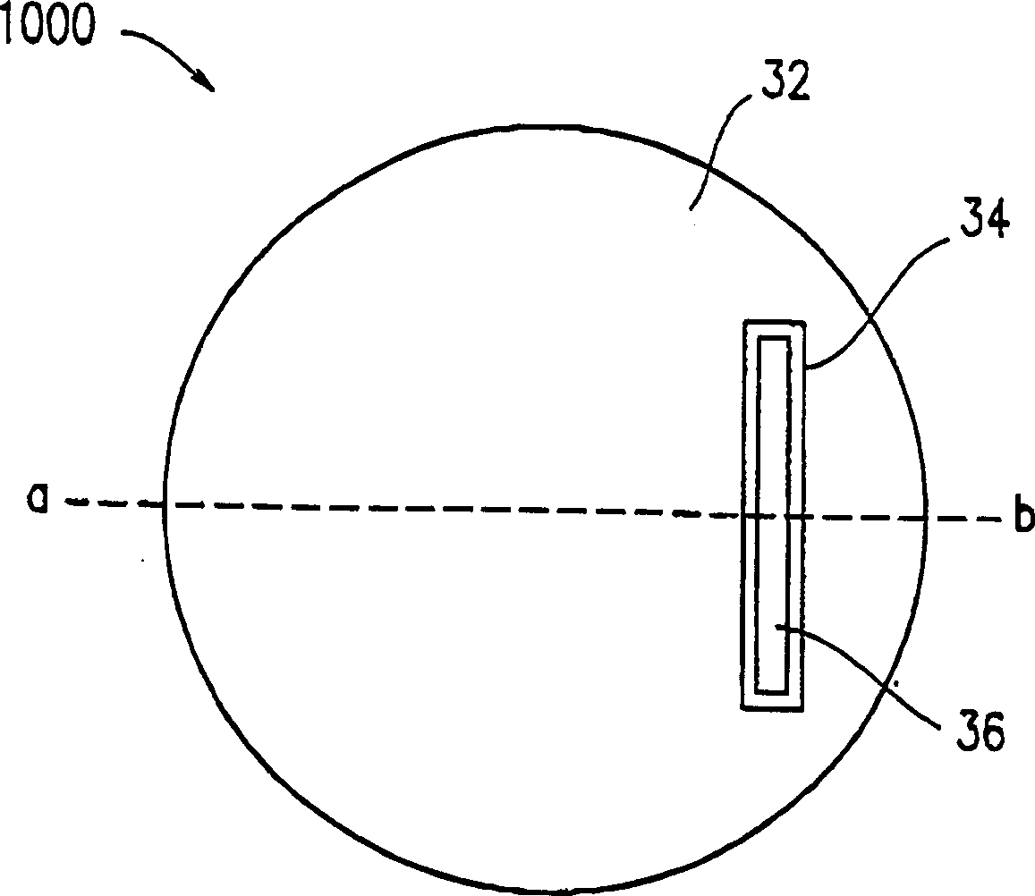
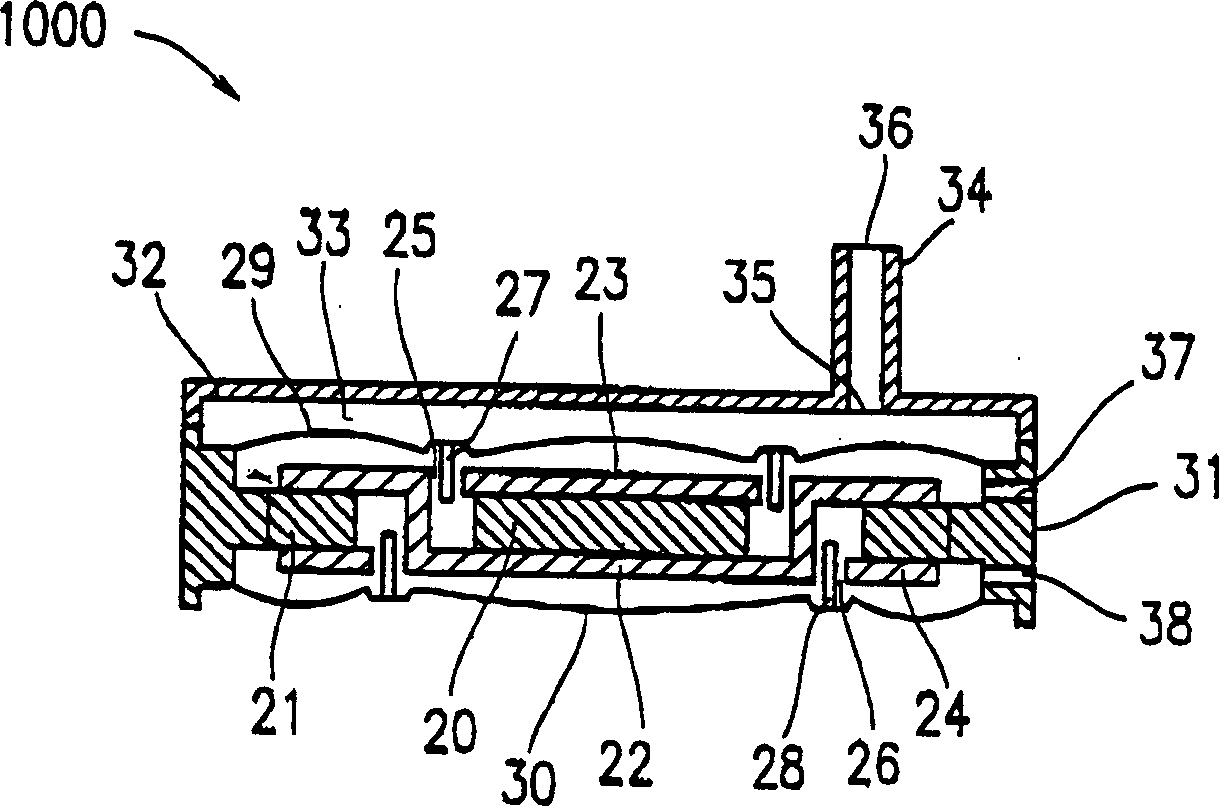
[0079] refer to Figure 1A and 1B , the speaker 1000 according to the first embodiment of the present invention will be described. Figure 1A is a plan view of speaker 1000, Figure 1B is a cross-sectional view of loudspeaker 1000 taken along dashed line a-b in FIG.

[0080] The loudspeaker 1000 includes a cylindrical first magnet 20; an annular second magnet 21 arranged to surround the first magnet 20; a yoke 22 for integrally connecting the first magnet 20 and the second magnet 21; A first voice coil 27 in the first magnetic gap 25 between the magnet 20 and the yoke 22; a second voice coil 28 arranged in the second magnetic gap 26 between the second magnet 21 and the yoke 22; connected to the first The first vibrating membrane 29 of the voice coil 27; the second vibrating membrane 30 which is arranged opposite to the first vibrating membrane 29 with respect to the first magnet 20 and is connected to the second voice coil 28; is arranged on the first vibrating membrane 29 an...

Embodiment 2

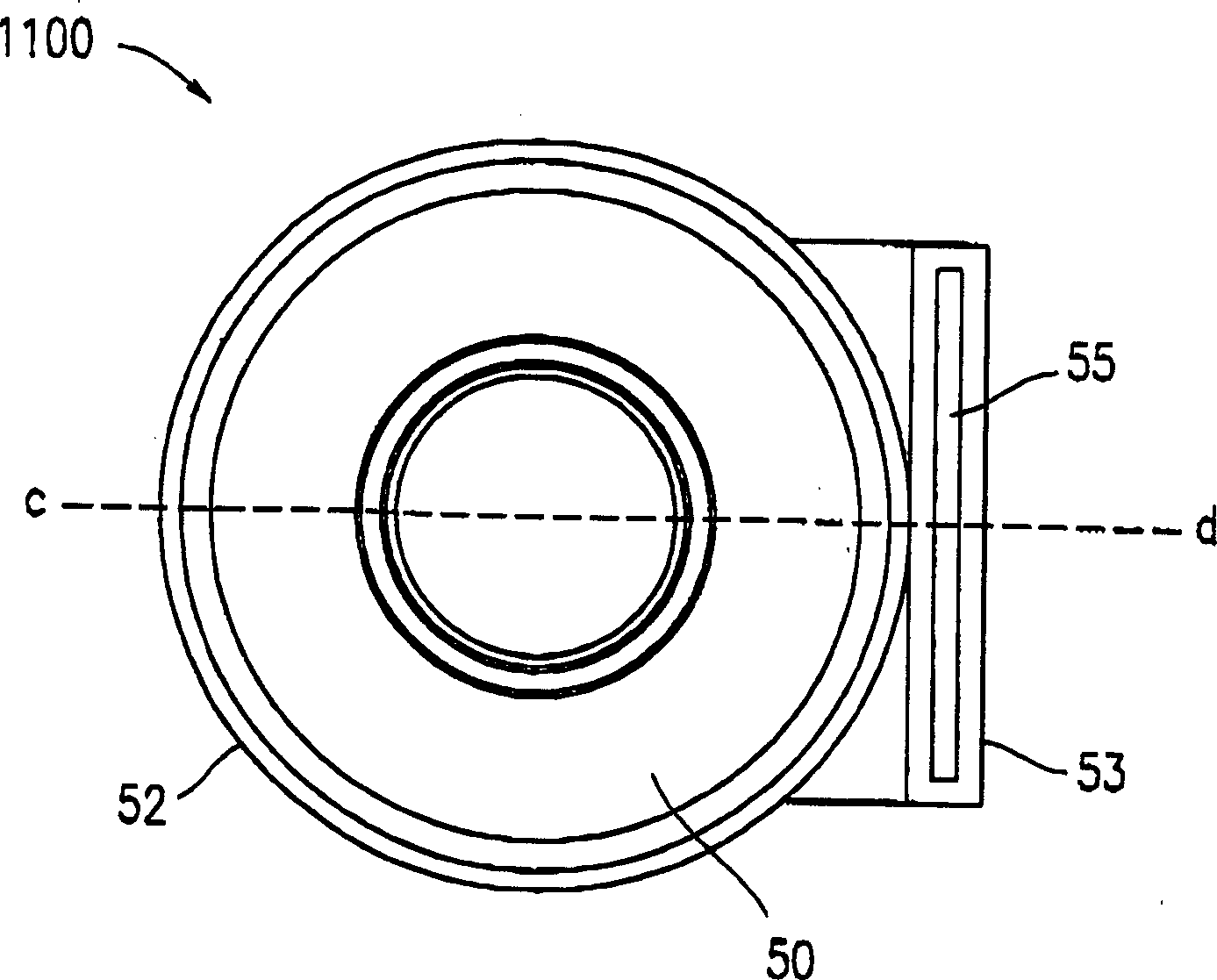
[0091] refer to Figure 2A and 2B , a speaker 1100 according to a second embodiment of the present invention will be described. Figure 2A is a plan view of speaker 1100, Figure 2B is along Figure 2A The cross-sectional view of the loudspeaker 1100 taken by the dotted line c-d in .

[0092] Loudspeaker 1100 comprises a yoke 43; Be arranged to surround a ring magnet 40 of yoke 43; Be arranged in the first voice coil 48 in the first magnetic gap 46 between yoke 43 and magnet 40; Be arranged between yoke 43 and magnet 40 The second voice coil 49 in the second magnetic gap 47 between them; the first vibrating membrane 50 connected to the first voice coil 48; set opposite to the first vibrating membrane 50 with respect to the yoke 43 and connected to the second voice coil 49 The second vibrating membrane 51; the first annular magnetic plate 41 arranged between the first vibrating membrane 50 and the magnet 40; the second annular magnetic plate 42 arranged between the second v...

Embodiment 3

[0105] refer to Figure 3A , 3B and 4, a speaker 1200 according to a third embodiment of the present invention will be described. Figure 3A is a plan view of speaker 1200, Figure 3B is along Figure 3A A cross-sectional view of the loudspeaker 1200 taken by the dotted line e-f in . Figure 4 is a perspective view of the yoke 63 described below.

[0106] Loudspeaker 1200 comprises a yoke 63; Be arranged to surround a ring magnet 60 of yoke 63; Be arranged in the first voice coil 69 in the first magnetic gap 67 between yoke 63 and magnet 60; Be arranged between yoke 63 and magnet 60 The second voice coil 70 in the second magnetic gap 68 between them; the first vibrating membrane 71 connected to the first voice coil 69; set opposite to the first vibrating membrane 71 with respect to the yoke 63 and connected to the second voice coil 70 The second vibrating membrane 72; the first annular magnetic plate 61 arranged between the first vibrating membrane 71 and the magnet 60; t...


PUM


Abstract

A loudspeaker comprising a first magnet; a second magnet arranged to surround the first magnet; a yoke for connecting the first magnet and the second magnet; a first voice coil; a second voice coil; a first vibrating membrane of the voice coil; a second vibrating membrane disposed opposite to the first vibrating membrane with respect to the first magnet and connected to the second voice coil; a first vibrating membrane disposed between the first vibrating membrane and the first magnet a magnetic plate; and a second magnetic plate disposed between the second diaphragm and the second magnet, wherein the first voice coil is disposed in the first magnetic gap between the first magnetic plate and the yoke, and the second voice coil is disposed in the second magnetic gap between the second magnetic plate and the yoke.

Description

technical field [0001] The present invention relates to a speaker including a plurality of vibrating membranes and a mobile terminal device on which such a speaker is mounted. Background technique [0002] A speaker comprising a magnetic circuit and two diaphragms is disclosed, for example, in Japanese Patent Applications 62-277000, 4-135096 and 11-252683. Japanese Patent Application No. 11-252683 will be described below. [0003] FIG. 22 is a sectional view of a speaker 3000 disclosed in Japanese Patent Application No. 252683. The loudspeaker 3000 includes a pole piece 1, a yoke 2 and a ring magnet 3, wherein the pole piece 1 has a recessed portion having a hole 14 at its center, and the yoke 2 is recessed at its center And has a hole 13 , the ring magnet 3 is fixed between the pole piece 1 and the yoke 2 . The yoke 2 functions as a frame. The loudspeaker 3000 has a first magnetic gap 4 on the outside of the magnet 3 and a second magnetic gap 5 on the inside of the magn...

Claims


Application Information

Patent Timeline
Patent Type & Authority Applications(China)
IPC IPC(8): H04M1/03H04M1/60H04R1/22H04R9/04
CPCH04M1/03H04M1/6041H04R1/025H04R1/225H04R9/045H04R2209/026H04R2499/11H04R2499/15
Inventor 佐伯周二薄木佐和子
Owner PANASONIC CORP
Why Eureka
Try Eureka