Method for detecting non-planeness defect

A technology of unevenness and detection area, which is applied in the direction of tension measurement, measuring device, electric device, etc., and can solve the problem that the unevenness measuring roller cannot be used

Inactive Publication Date: 2003-01-01
CLECIM SAS
View PDF5 Cites 17 Cited by
  • Summary
  • Abstract
  • Description
  • Claims
  • Application Information

AI Technical Summary

Problems solved by technology

[0029] The consequence is that, until now, in the case of hot rolling, it seems impossible to use conventional types of roughness measuring rolls

Method used


Image

  • Method for detecting non-planeness defect
  • Method for detecting non-planeness defect
  • Method for detecting non-planeness defect

Examples


Embodiment Construction

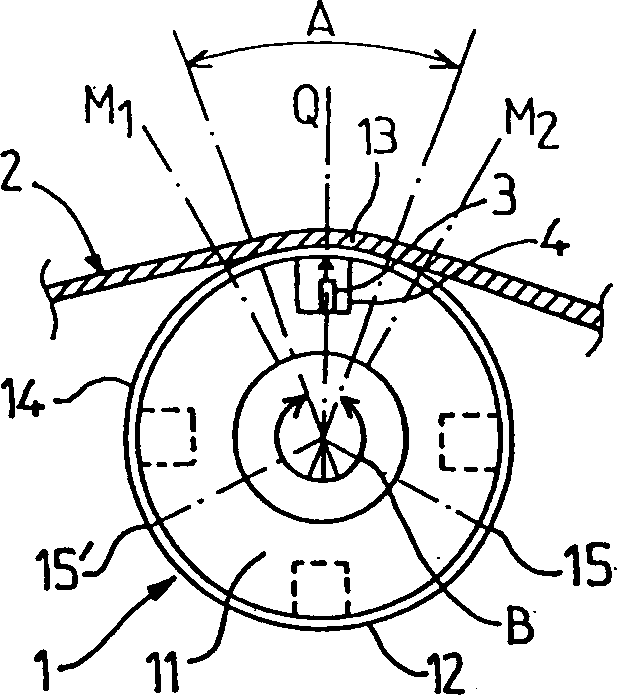
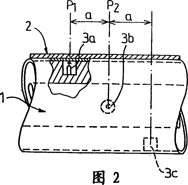
[0053] figure 1 and 2 schematically represent an unevenness measuring roll 1 to which a strip 2 is applied (applied) under tensile load, the strip 2 covering one of the angular sectors A of the roll 1 .

[0054] The roll 1 consists, in a known manner, of a corrosion-resistant (durable) tubular body 11 covered with a thin annular cladding 12 .

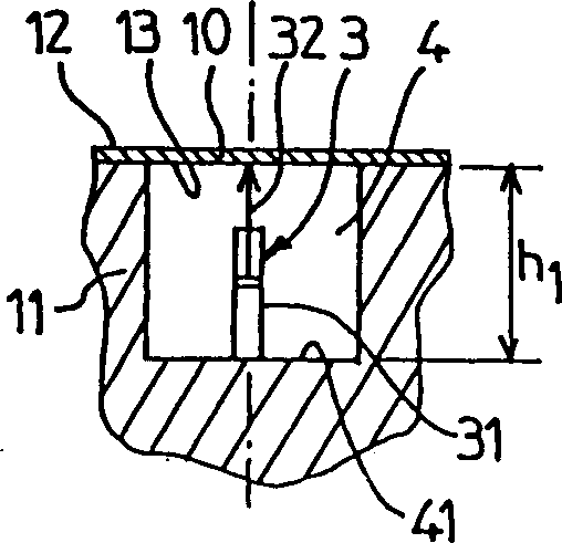
[0055] The roll 1 is equipped with a plurality of measuring sensors 3, each of which is arranged in a recess 4, for example in a blind hole drilled in the corrosion resistant body 11, and these recesses form the sensor 3 protective walls A section 10 of the thin cladding 12 is closed to the outside.

[0056] As shown in Figure 2, each sensor 3 is axially spaced apart by a pitch (a), and is distributed in a spiral shape on the entire length of the roller, so that two adjacent sensors 3a, 3b are staggered by an angle for Easier measurement handling.

[0057] All of these configurations are well known and require no elaboration.

[005...


PUM


Abstract

The object of the invention is a process for detecting latent flatness defects in a band product (2) applied under tensile load to an angular sector (A) of measuring roll (1) comprising a plurality of detection zones (4) spaced apart each comprising a transmission sensor (3), at each rotation, of a measurement signal having a value under load (i) which is compared, at each rotation, with a reference value, in order to assess, in each longitudinal zone of the band (2), information representative of the tensile load applied in this zone. According to the invention, two values in empty condition (i1, i2) of the signal transmitted by each sensor (3) are measured, respectively before and after the corresponding detection zone passes through the angular application sector (A) of the band and the reference value (i0) to which is compared, at each rotation, the value under load (i) of the signal transmitted by each sensor is obtained by combination of said values in empty condition, respectively preceding (i1) and subsequent (i2).

Description

technical field [0001] The present invention relates to a method and a device for detecting potential unevenness (flatness) defects of metal strip products running in the longitudinal direction. Background technique [0002] When rolling metal strip, especially thin rolled plate, roughness defects can be observed once the strip is in a rest position, but when said strip is kept under tensile load, that roughness defect material may be in a latent state. These defects are generally due to small variations in strip width due to elongation by the rolling method, and these defects can be affected by the rolling conditions, and especially in the transverse direction, adding Correction is made in the distribution of the clamping pressure between the individual work rolls. [0003] For this reason, modern rolling mills are usually equipped with devices that correct the profile of the gap through which the products pass. [0004] Often the stands of rolling mills are equipped wit...

Claims


Application Information

Patent Timeline
Patent Type & Authority Applications(China)
IPC IPC(8): G01B7/34G01L5/04
CPCG01L5/045G01B7/345
Inventor T·梅勒德J-P·富尔
Owner CLECIM SAS
Why Eureka
Try Eureka