

Acoustic surface wave filter
A surface acoustic wave and filter technology, which is applied in the field of surface acoustic wave filters, can solve the problem of uniformity decrease in insertion loss, and achieve the effect of reducing deviation and improving uniformity
- Summary
- Abstract
- Description
- Claims
- Application Information
AI Technical Summary
Problems solved by technology
Method used
Image

Examples
no. 1 example
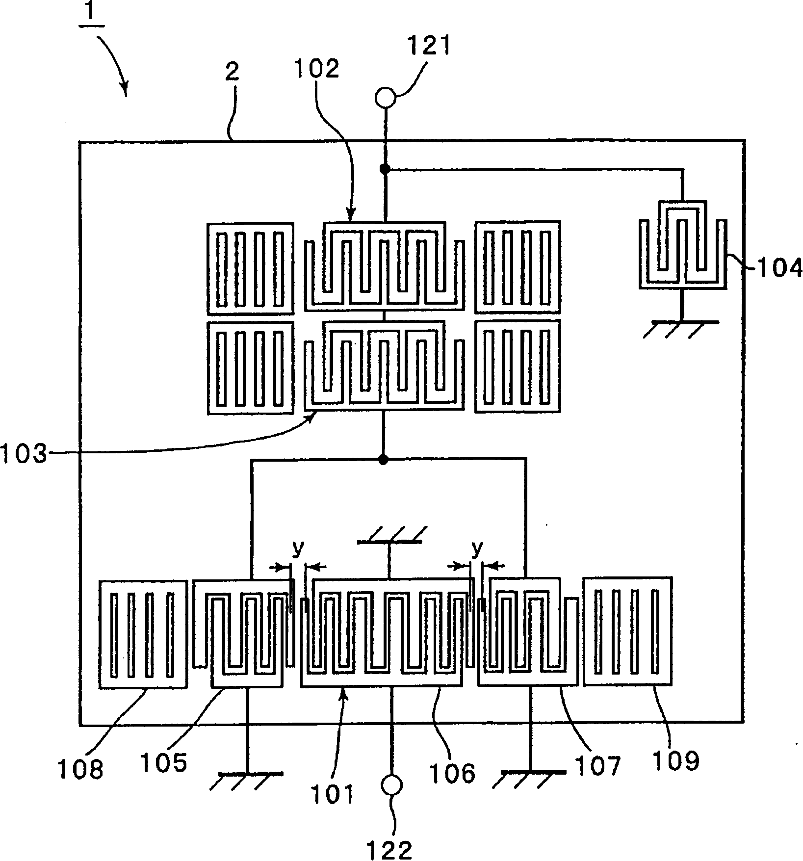
[0037] figure 1 is a plan view illustrating the SAW filter 1 according to the first embodiment of the present invention. In the following embodiments, SAW filters are discussed in the context of Personal Cellular Network (PCS) transmission filters.
[0038] In this embodiment, a piezoelectric substrate 2 made of a 40±5° Y-cut X-propagation lithium niobate (LiTaO3) substrate is used. On the piezoelectric substrate 2, a longitudinally coupled resonator mode SAW filter section 101, and SAW resonators 102, 103, and 104 are formed from aluminum (Al) electrodes. The SAW resonators 102 and 103 are connected in series with each other between the SAW filter section 101 and the input signal port 121 . The SAW resonator 104 is connected in parallel with the SAW filter section 101 . That is, the SAW resonator 104 is connected between the input port and the ground port.
[0039] In the SAW filter section 101, IDTs 105, 106, and 107 are arranged in the SAW propagation direction, and ref...
no. 2 example
[0100] Figure 11 is a plan view illustrating an electrode structure of a SAW filter according to a second embodiment of the present invention. As in the SAW filter of the first embodiment, in the SAW filter of the second embodiment, a 40±5° Y-cut X-propagation LiTaO3 (lithium niobate) substrate is used, but not shown, and the electrodes are arranged at on the substrate. Figure 11 It is shown that the electrode structure of the SAW filter of the second embodiment is similar to that of the first embodiment except for the structure of the SAW resonator 204 connected in parallel with the SAW filter section 101 . More specifically, in the SAW resonator 204, the reflectors 123 and 124 are disposed on the left and right of the IDT 120, respectively. Other performances of the second embodiment are similar to those of the first embodiment, therefore, the same elements as those of the first embodiment are indicated by the same numbers, and their examples are omitted.
[0101] Excep...
no. 3 example
[0116] Figure 15 A plan view showing an electrode structure of a SAW filter according to a third embodiment of the present invention is shown.
[0117] The structure of the third embodiment SAW filter is similar to that of the first embodiment except that the center IDT 106 of the SAW filter section 101 of the longitudinally coupled resonator mode is connected to a pair of balanced signal ports 301 and 302 . By connecting the central IDT106 of the SAW filter part 101 with a pair of balanced signal ports 301 and 302, a SAW filter with a balanced-unbalanced conversion function is provided, wherein the input terminal 121 is used as an unbalanced signal terminal and a balanced Signal terminals 301 and 302.
[0118] Therefore, the third embodiment is constructed in a similar manner to the first embodiment except that a balanced-unbalanced conversion function is provided. Thus, according to the third embodiment, it is possible to provide a SAW filter having a balun function and h...
PUM
| Property | Measurement | Unit |
|---|---|---|
| Wavelength | aaaaa | aaaaa |
Abstract
Description
Claims
Application Information