Radio transmitting apparatus and radio transmitting method
A technology for wireless transmission and wireless reception devices, applied in the field of wireless transmission devices, which can solve the problems of being difficult to suffer from frequency selective fading, deterioration of error rate characteristics, and inability to fully track lines, etc.
- Summary
- Abstract
- Description
- Claims
- Application Information
AI Technical Summary
Problems solved by technology
Method used
Image
Examples
Embodiment 1
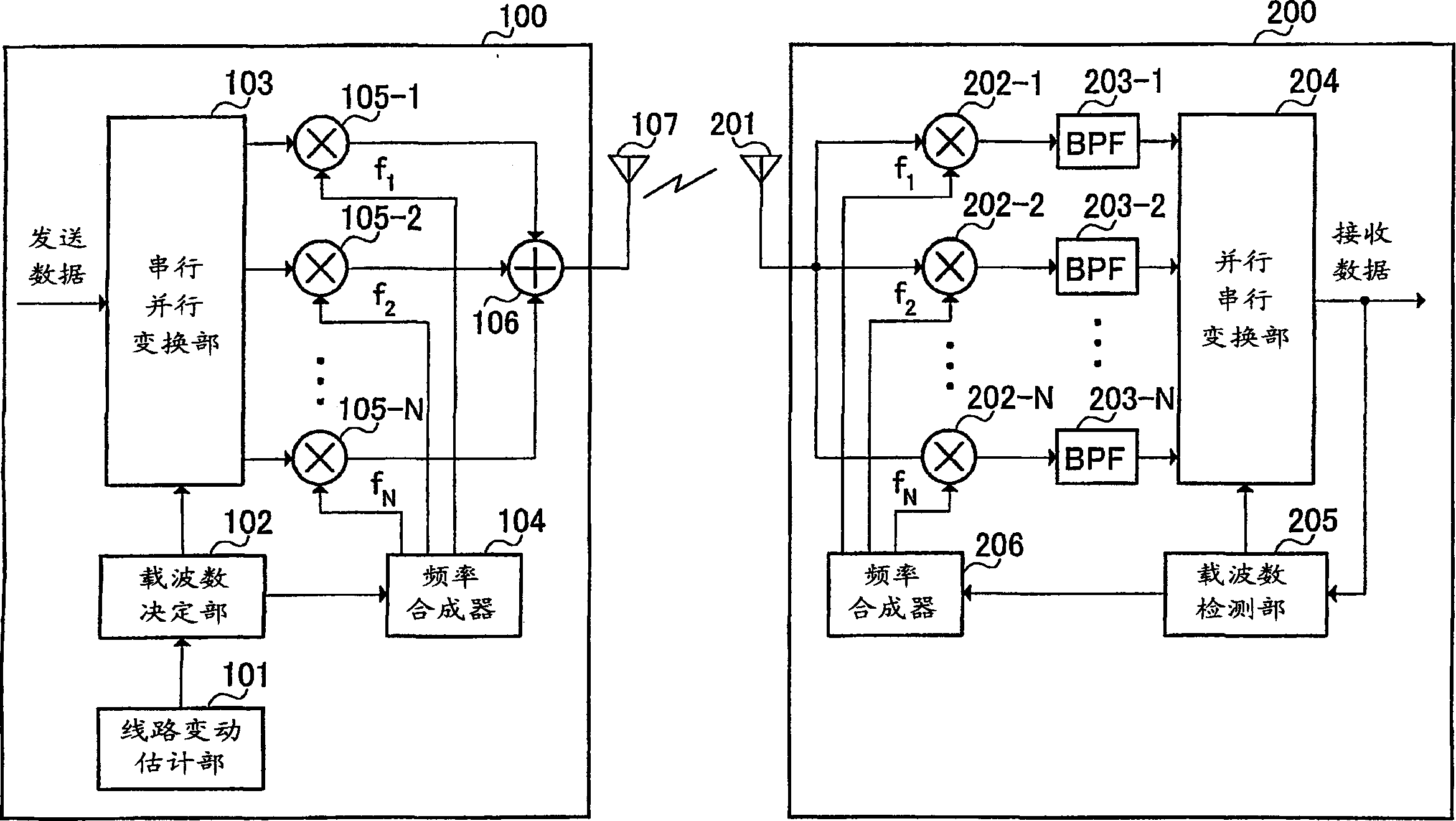
[0024] figure 1 It is a block diagram showing the structures of the transmitting device and the receiving device according to Embodiment 1 of the present invention.
[0025] exist figure 1 In the transmission device 100 shown, the channel fluctuation estimation unit 101 estimates the channel fluctuation amount between the transmission device 100 and the reception device 200 , and outputs the estimation result to the carrier number determination unit 102 . In addition, as a method of estimating the amount of channel variation, the method of measuring the reception level of a signal received by a receiving device (not shown) mounted in a base station device or the like together with the transmitting device 100, and estimating it based on the measurement result .
[0026] The carrier number determination unit 102 determines the number of carriers used for signal transmission based on the estimated amount of channel variation. In addition, the number-of-carriers determination u...
Embodiment 2
[0050] In the transmission device of this embodiment, in OFDM (Orthogonal Frequency Division Multiplexing; Orthogonal Frequency Division Multiplexing) modulation, the greater the channel variation, the more the number of carriers is reduced to transmit signals.
[0051] Here, OFDM is a multi-carrier modulation method, and is a modulation method in which carriers are in an orthogonal relationship.
[0052] Figure 7 It is a structural block diagram of the transmitting device and the receiving device according to Embodiment 2 of the present invention. Among them, in Figure 7 In the sending device and receiving device shown, pair with figure 1 The same structural part is appended with figure 1 The same reference numerals are used, and descriptions thereof are omitted.
[0053] exist Figure 7 In the transmission device 100 shown, the carrier number determination unit 102 outputs a signal indicating the determined number of carriers to the serial-parallel conversion unit 103...
Embodiment 3
[0062] In this embodiment, the transmitting device does not determine the number of carriers, and the transmitting device transmits data based on the number of carriers determined by the receiving device.
[0063] Figure 8 It is a structural block diagram of a sending device and a receiving device according to Embodiment 3 of the present invention. Among them, in Figure 8 In the sending device and receiving device shown, pair with figure 1 The same structural part is appended with figure 1 The same reference numerals are used, and descriptions thereof are omitted.
[0064] exist Figure 8 In the shown receiving apparatus 200 , the channel fluctuation estimation unit 210 estimates the channel fluctuation amount of the multi-carrier signal, and outputs the estimation result to the carrier number determination unit 211 .
[0065] The carrier number determination unit 211 determines the number of carriers used for signal transmission by the transmission device 100 based on ...
PUM
 Abstract
Description
Claims
Application Information
 - R&D
- Intellectual Property
- Life Sciences
- Materials
- Tech Scout
- Unparalleled Data Quality
- Higher Quality Content
- 60% Fewer Hallucinations
Browse by: Latest US Patents, China's latest patents, Technical Efficacy Thesaurus, Application Domain, Technology Topic, Popular Technical Reports.
© 2025 PatSnap. All rights reserved.Legal|Privacy policy|Modern Slavery Act Transparency Statement|Sitemap|About US| Contact US: help@patsnap.com


