Confocal microscope

A confocal microscope and microscope technology, applied in the field of confocal microscopes, can solve the problems of loss of measurement accuracy, difficulty in improving, difficulty in making a large numerical aperture, etc., and achieve the effect of improving accuracy and improving Z-direction resolution

Inactive Publication Date: 2003-02-05
NAT INST OF METROLOGY CHINA
View PDF1 Cites 48 Cited by
  • Summary
  • Abstract
  • Description
  • Claims
  • Application Information

AI Technical Summary

Problems solved by technology

The three-dimensional shape often has multiple extremely high points that are higher than the surrounding areas. The heights of these many extremely high points may not exactly coincide with the focal plane of a certain scan. Infer the amount of defocus, and the size of the luminous flux is not only related to the defocus condition, but also related to processing conditions, materials and even the inclination of the measured surface, etc., resulting in the loss of measurement accuracy
In addition, the resolution in the Z direction is related to the numerical aperture and magnification of the objective lens, but the increase of the magnification of the objective lens has a great impact on the application range of the instrument, and it is difficult to make the numerical aperture large
Therefore, at present, the measurement accuracy of the general confocal microscope in the Z direction is only a few tenths of a micron, which is difficult to improve.

Method used


Image

  • Confocal microscope
  • Confocal microscope
  • Confocal microscope

Examples


Embodiment approach

[0027] a. Dual-frequency interferometry scheme; b. Single-frequency polarization interferometry (with phase subdivision) scheme.

[0028] In each embodiment, in terms of specific geometrical optical paths, the following can be used: the optical path of the objective lens with infinite barrel length and the optical path of the objective lens with finite barrel length. In order to obtain the desired signal more reliably, in terms of the receiving optical path, the interference signal and the confocal signal can be received separately and mixed to receive two different structural forms. They are described as follows.

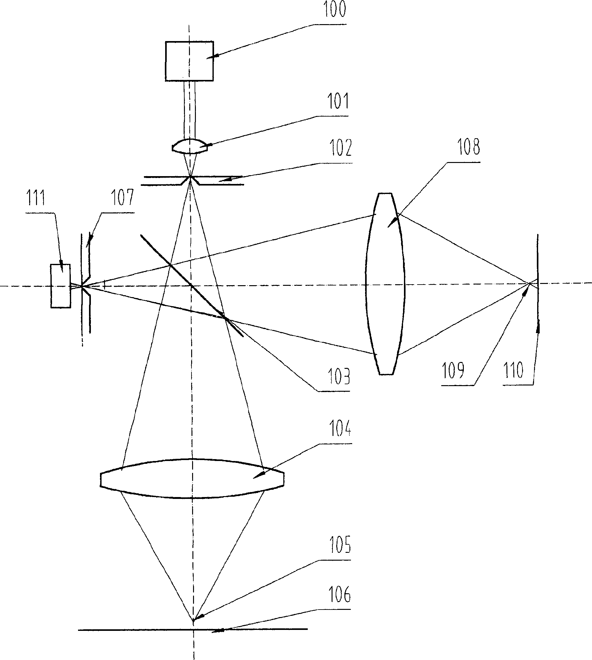
[0029] 1) Dual-frequency interference confocal microscope

[0030] see Figure 5 , using the dual-frequency laser 201 with two optical frequencies or wavelengths as the light source, a high-brightness point light source is formed on the pinhole of the diaphragm 203 through the condenser lens 202, and the light enters the beam splitter after passing through the co...


PUM


Abstract

The invented confocal microscope includes the light source part, the beam splitter mirror, the object lens, the worktable used for placing the sample, the conjugate diaphragm and the first detector. The beam splitter mirror splits the incident light into the transmission light and the reflected light. The conjugate diaphragm is conjugated with the focus point of the object lens. The light source part generates the coherent light. The microscope also includes the reflector. One of the transmitted light or reflected light through the object lens irradiates the sample. The other light irradiates the reflector. The light reflected from the sample passes the object lens, going to the beam splitter mirror where it meets the light reflected from the reflector so as to form the interference figure output from the conjugate diaphragm.

Description

technical field [0001] The invention relates to a confocal microscope, which can measure the three-dimensional topography of a sample. Background technique [0002] In the optical instrument industry, there is a type of instrument called a microscope, which can measure the length and width of an object. However, in scientific research and production, there are often situations that require measuring the height value of each X and Y coordinate, such as the surface to be processed. roughness, etc. In this way, a new optical instrument that can measure three-dimensional topography - confocal microscope appeared in 1957. Its patent is shown in the US patent US3013467 granted by Minisky M in 1961, and its invention name is Microscopy apparatus. See Minisky for related articles. M1988 Memoiron inventing the confocal scanningmicroscope scanning. [0003] The principle of a general confocal microscope is shown in figure 1 , the light emitted from the pinhole illumination light so...

Claims


Application Information

Patent Timeline
Patent Type & Authority Applications(China)
IPC IPC(8): G02B21/00
Inventor 邵宏伟徐毅高思田叶孝佑陈允昌许捷李晶
Owner NAT INST OF METROLOGY CHINA
Why Eureka
Try Eureka