Supercharge Your Innovation With Domain-Expert AI Agents!

Angular rate sensor

A technology of angular velocity sensor and resonator, applied in the direction of gyro effect for speed measurement, instrument, speed/acceleration/shock measurement, etc.

Inactive Publication Date: 2003-02-12
ATLANTIC INERTIAL SYST
View PDF2 Cites 6 Cited by
  • Summary
  • Abstract
  • Description
  • Claims
  • Application Information

AI Technical Summary

Problems solved by technology

These techniques and processes employed at the foundry cannot be directly applied to [111] diced silicon wafers

Method used


Image

  • Angular rate sensor
  • Angular rate sensor
  • Angular rate sensor

Examples


Embodiment Construction

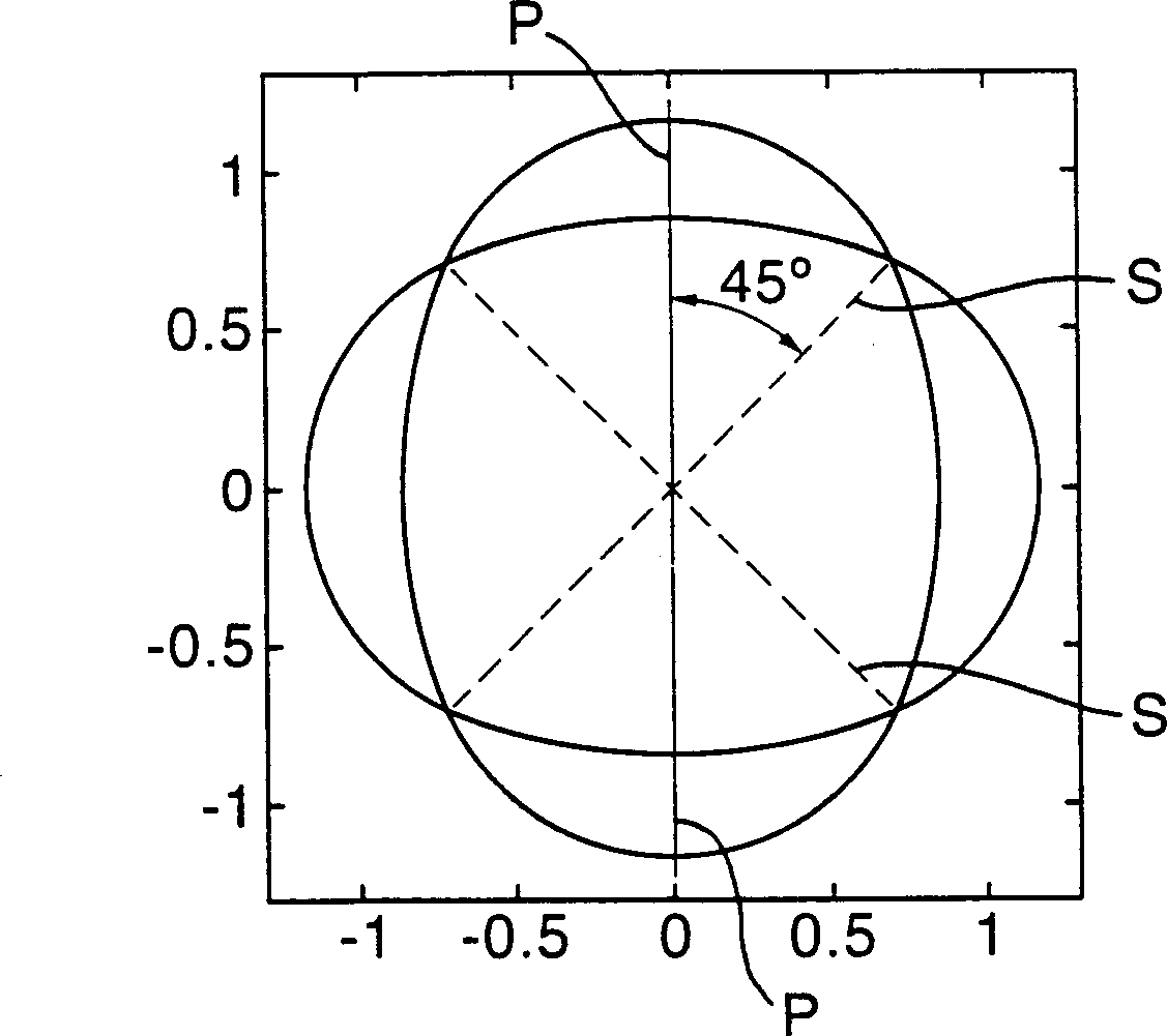
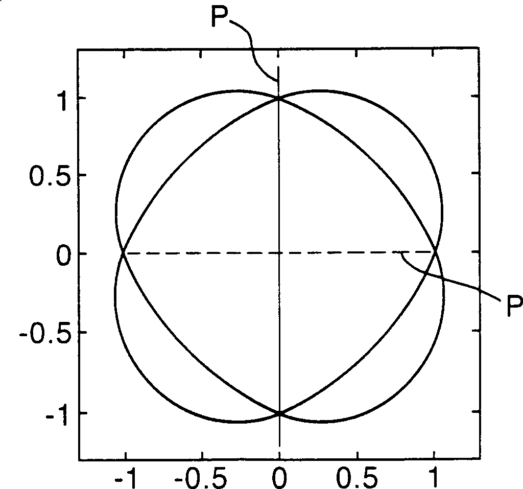
[0029] An angular velocity sensor device embodying the present invention will now be described with reference to FIGS. 3a , 3b , 4 and 5 . The sensor device 10 comprises a micromachined vibrating structure gyroscope and is arranged to operate in the Sin3Θ and Cos3Θ vibrational mode pairs as described above. More specifically, Cos 3θ carrier and Sin 3θ response pattern patterns are shown in Figures 3a and 3b.

[0030] The device 10 utilizing these modes incorporates electrostatic and capacitive drive transducers similar to those described in GB9817347.9. The manufacturing process used to produce this structure is basically the same as that described in GB9828478.9, so it will not be repeated below.

[0031] Device 10 is formed from a layer of [100] conductive silicon wafer 12 anodically bonded to a glass substrate 14 . The main components of the device 10 are the ring structure resonator 16 , six drive capacitive transducers 18 and six sensor capacitive transducers 20 . The re...


PUM


Abstract

An angular rate sensor device (10) such as a micro-machined vibrating structure gyroscope, comprises a resonator (16), drive means (18), sensing means (20) and associated electronic control means. The resonator (16), drive means (18), sensing means (20) and control means are fabricated from a layer of crystalline silicon (12) having a [100] principal crystal plane. In order to make the resonator (16) operate in this type of material without degrading its performance, the resonator (16) is arranged to be operated by the drive and sensing means (18, 20) under the control of the electronic control means with a vibration mode pair having modal parameters, such as Young's Modulus, matched to provide a consistent resonator response. In particular, the resonator (16) is arranged to be operated with a Sin 3theta / Cos 3theta (vibration mode pair providing degenerate carrier and response parameters.

Description

technical field [0001] The present invention relates to improvements in angular velocity sensor devices, and more particularly, but not exclusively, to angular velocity sensor devices employing sensors having vibrating resonators with planar structures, such as those used in micromachined vibrating structure gyroscopes (VSG) and related in the control electronics. Background technique [0002] Micromachined vibrating structure gyroscopes, ie, VSGs etched into single-crystal silicon substrates, provide a source of small, low-cost rate sensors that can be supplied in large quantities. This affordability has created new huge markets, especially in the field of automotive applications. Many devices are currently being developed using a variety of sensor chip configurations constructed using different materials and processes. The completed device consists of a sensor chip and associated control electronics in a suitable package. For high volume applications, these control elec...

Claims


Application Information

Patent Timeline
Patent Type & Authority Applications(China)
IPC IPC(8): B81B3/00G01C19/5684H01L29/84
CPCG01C19/5684G01C19/56
Inventor 克里斯托弗·P·费尔
Owner ATLANTIC INERTIAL SYST
Features
  • R&D
  • Intellectual Property
  • Life Sciences
  • Materials
  • Tech Scout
  • Unparalleled Data Quality
  • Higher Quality Content
  • 60% Fewer Hallucinations
Learn More