System and method of optical switch

A switch and optical fiber technology, which is applied in the field of optical switches and can solve the problems of complex cross-connect switches.

Inactive Publication Date: 2003-02-19
LUMENTUM OPERATIONS LLC
View PDF0 Cites 13 Cited by
  • Summary
  • Abstract
  • Description
  • Claims
  • Application Information

AI Technical Summary

Problems solved by technology

However, full cross-connect switches are often

Method used


Image

  • System and method of optical switch
  • System and method of optical switch
  • System and method of optical switch

Examples


Embodiment Construction

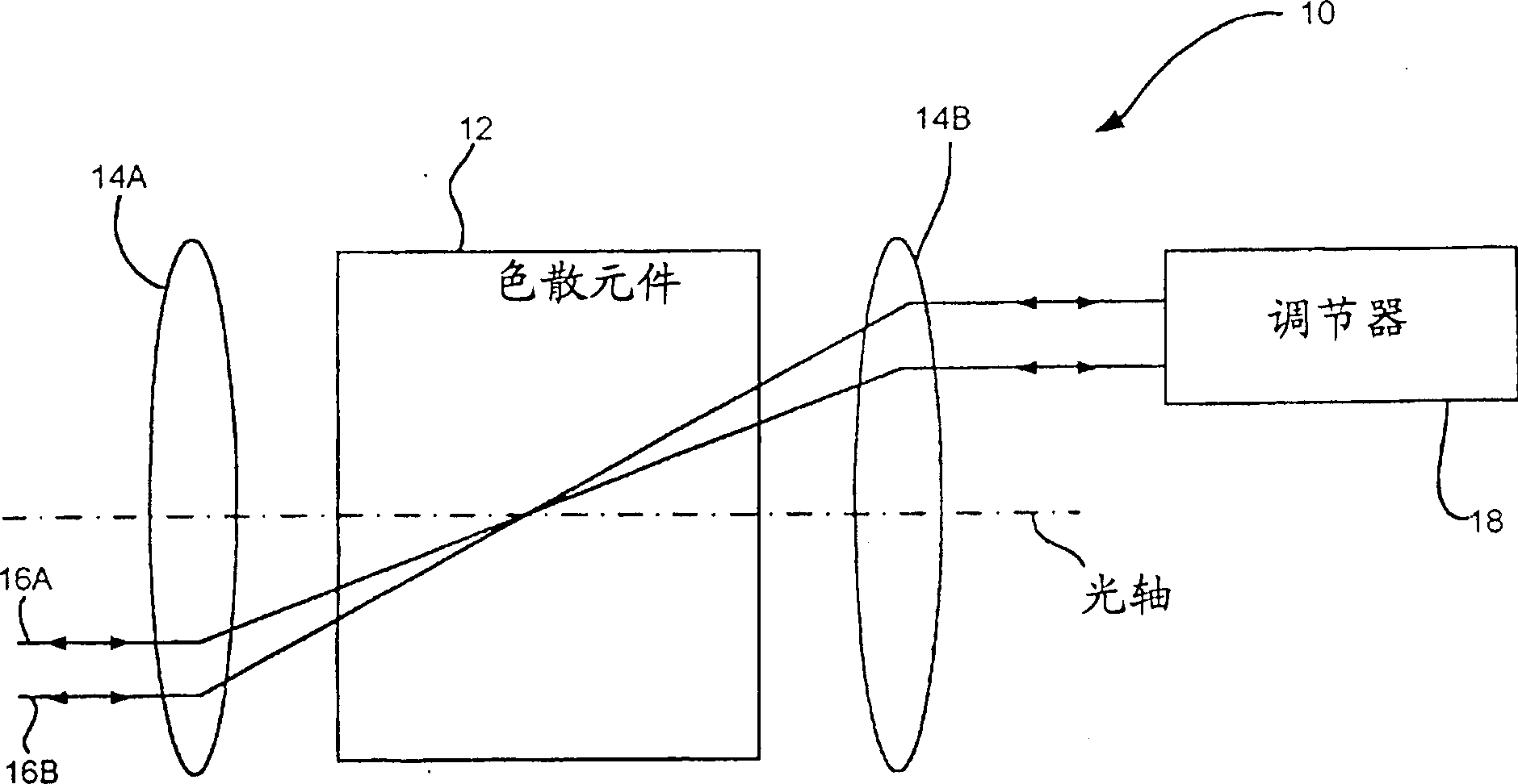
[0027] figure 1 General optics 10 for rerouting and conditioning optical signals are shown. Optical device 10 comprises a dispersive element 12 (prism, diffraction grating, etc.) positioned between elements 14A and 14B having optical power and in the focal plane of elements 14A and 14B. Two ports 16A and 16B on the input / output side are shown as double-headed arrows, where light emitted to port 16A can propagate through optics 10 and can be reflected back to input port 16A, or converted in a controlled manner to port 16B and vice versa. Although only two input / output ports are shown to facilitate understanding of device 10, a plurality of such ports may be provided. Optical device 10 also includes a modulator 18 for modulating at least a portion of the incident light.

[0028] Modulator 18 and / or dispersive element 12 typically depends on the polarization of the incident light. In particular, light is provided with a known polarization state in order to obtain selected con...


PUM


Abstract

A fiber optic wavelength switch that includes a front-end unit having optical ports for receiving and transmitting optical signals; a wavelength dispersion element (e.g., diffraction grating, prism, etc.) for defining a dispersion plane; a light redirecting element (e.g., spherical reflector) associated with the wavelength dispersion element; and an actuation array (e.g., MEMS) operative with the light redirecting element for tilting an optical signal substantially perpendicular to the dispersion plane defined by the wavelength dispersion element. The wavelength switch can be implemented as a one input/output port and several add/drop ports type device, which can add/drop wavelengths from/to the in/out port. The front-end unit having a fiber array coupled to a micro-lens array with optical signals from the micro-lens being directed by a further lens.

Description

[0001] Referenced related patent applications [0002] This patent application benefits from US Provisional Patent Application Serial No. 60 / 304,407, filed July 12, 2001, entitled "Wavelength Switch With Multiple Tunable Optical Ports." technical field [0003] The present invention relates to an optical switch, in particular to an optical fiber wavelength switch with a plurality of adjustable optical ports. Background technique [0004] The growth of the Internet and other broadband services has increased the capacity requirements for long-distance and urban communications infrastructure. The increased fiber optic system bandwidth is usually not sufficient to meet this demand, and the shortage of fiber optic resources has become the focus of attention of many network operators. In the past, a practical technology capable of meeting higher broadband requirements at a defined baud rate was Dense Wavelength Division Multiplexing (DWDM), which mixes multiple wavelengths of lig...

Claims


Application Information

Patent Timeline
IPC IPC(8): G02B6/34G02B6/35
CPCG02B6/3512G02B6/3592G02B6/29373G02B6/272G02B6/2931G02B6/356
Inventor 托马斯·杜瑟里尔飞利浦思·S·洛克斯雅克·比思姆斯
Owner LUMENTUM OPERATIONS LLC
Why Eureka
Try Eureka