Loom transmission

A transmission device and loom technology, applied in looms, textiles, textiles and papermaking, etc., can solve problems such as high price of brakes and clutches, reduced performance of looms, and easy wear and tear, and achieve optimal matching timing, simple structure, The effect of short service life

Inactive Publication Date: 2003-03-12
JINGWEI TEXTILE MASCH CO LTD
View PDF0 Cites 4 Cited by
  • Summary
  • Abstract
  • Description
  • Claims
  • Application Information

AI Technical Summary

Problems solved by technology

During the use of the loom, the brake and clutch are expensive and easy to wear. During the wear process

Method used


Image

  • Loom transmission
  • Loom transmission
  • Loom transmission

Examples


Embodiment Construction

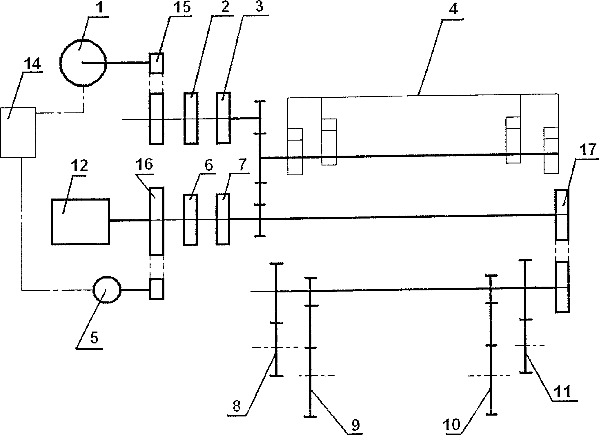
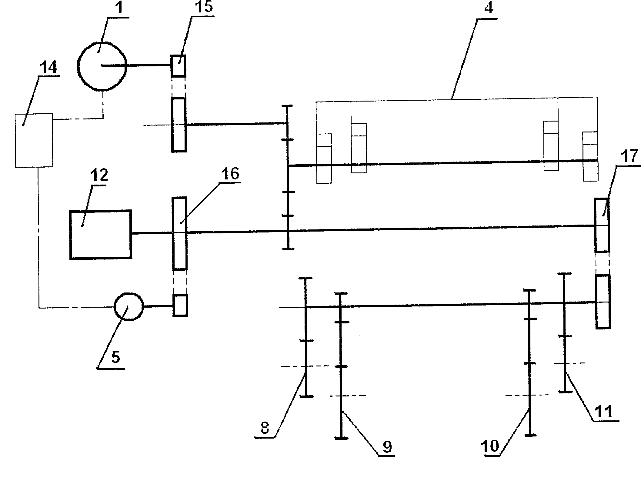
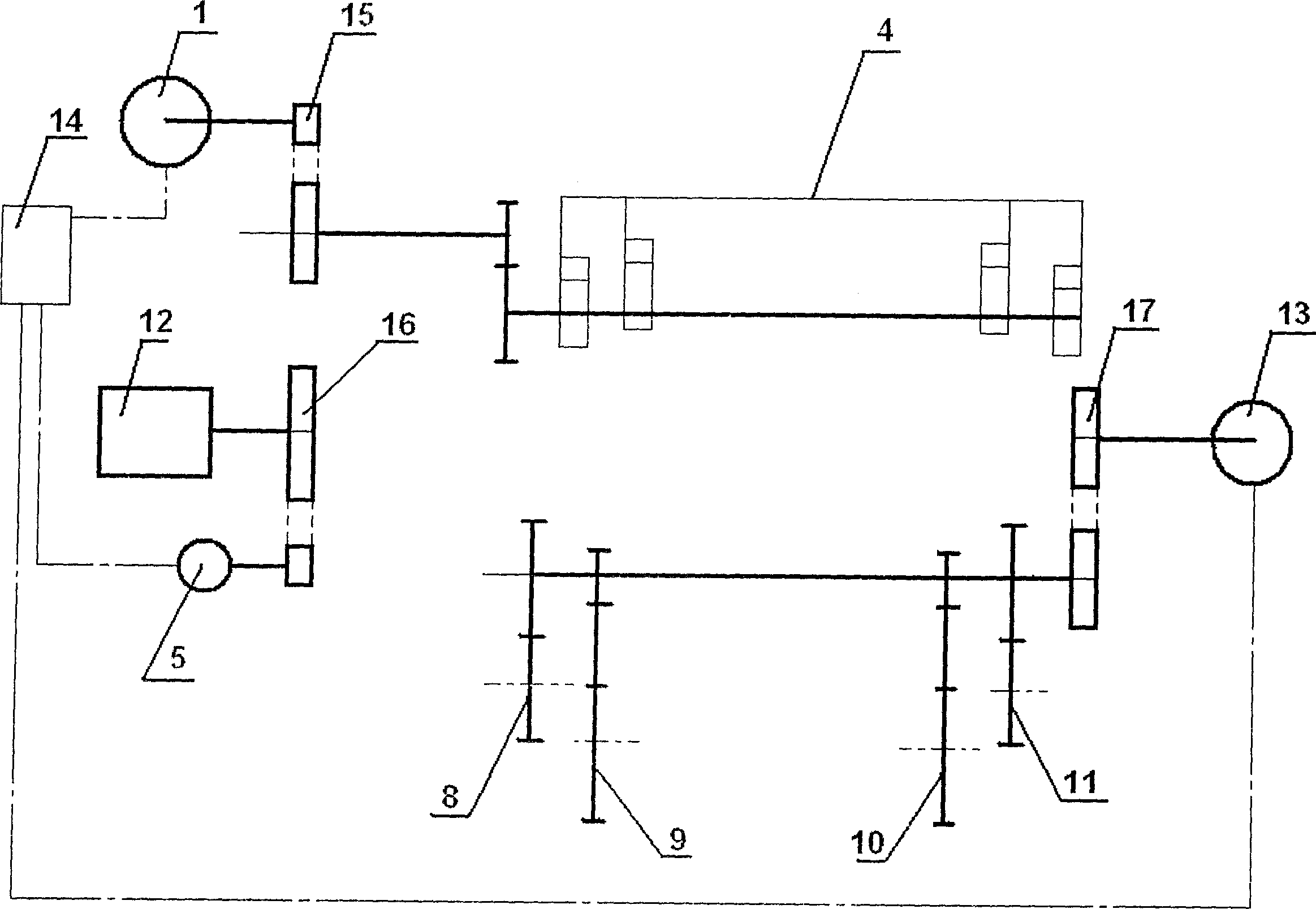
[0009] like figure 1 Shown, will usually clutch 2 in the loom transmission, after brake 3, mechanical linkage (ZX, ZY), weft-seeking clutch 6, slow clutch 7 are removed, change the hardware and the program of controller 14. The motions of the beating-up motor 1 and the shedding motor 5 are changed from the original mechanical synchronization to the electrical control synchronization of the controller 14 to meet the weaving performance of the loom. like figure 2 transmission shown. A kind of loom transmission device, it comprises beating-up motor 1, shedding motor 5, beating-up mechanism 4, shedding mechanism 12, back beam swing mechanism 8,11, hemming mechanism 9,10 and controller 14, and beating-up motor 1 passes The speed changer 15 is connected with the beating-up mechanism 4, the shedding motor 5 is connected with the shedding mechanism 12 by the speed changer 16, the speed changer 16 is connected with the speed changer 17, the speed changer 17 is connected with the bac...


PUM


Abstract

A loom driver is composed of beating up motor and mechanism, opening motor and mechanism, speed variators, back beam oscillating mechanism, selvedge binder mechanism, and controller. Its advantages are simple structure, and no need of expensive electromagnetic brake and clutch.

Description

1. Technical field: [0001] The invention belongs to a textile machine, in particular to a loom transmission device. 2. Background technology: [0002] In the existing loom transmission, such as figure 1 , the main motor 1 is connected with the main shaft through a clutch 2 and a brake 3 to drive the beating and shedding mechanism of the loom. There is also a slow motor 5 in addition, which is connected with the auxiliary shaft by a clutch 6. When the loom moves at a slow speed, the main clutch 2 is opened, and the weft-seeking clutch 6 and the slow clutch 7 are closed. When weft-seeking, the main clutch 2 and the slow clutch 7 are opened, and the weft-seeking clutch 6 is closed. The swing of the back beam is synchronized with the mechanical device and the opening mechanism. During the use of the loom, the brakes and clutches are expensive and easy to wear. During the wear process, the performance of the loom is also declining, and they need to be adjusted and replaced fre...

Claims


Application Information

Patent Timeline
IPC IPC(8): D03D51/02
Inventor 张庆喜
Owner JINGWEI TEXTILE MASCH CO LTD
Why Eureka
Try Eureka