Optical fiber with light-focusing function, and mfg. method thereof

A manufacturing method and optical fiber technology, which are applied in the directions of cladding optical fibers, optical waveguide light guides, and optical waveguide coupling, etc., can solve the problems of not being able to obtain good coupling between optical fibers and optical devices, and achieve easy operation, improved optical coupling efficiency, and improved manufacturing. The effect of efficiency

Inactive Publication Date: 2003-03-12
JAPAN AVIATION ELECTRONICS IND LTD
View PDF1 Cites 7 Cited by
  • Summary
  • Abstract
  • Description
  • Claims
  • Application Information

AI Technical Summary

Problems solved by technology

[0007] Therefore, even if the length of the GI optical fiber 12 is changed according to the type and size of the optical device coupled with the optical fiber, and the distance WD at the beam waist position is set to a predetermined value, the beam waist diameter and the optical beam waist diameter, which are changed in conjunction with each other, often occur. In the case where the device is not suitable, there is a difficulty that good coupling between the fiber and the optical device cannot be obtained by only adjusting the beam waist position by making the length of the GI fiber 12 variable.

Method used


Image

  • Optical fiber with light-focusing function, and mfg. method thereof
  • Optical fiber with light-focusing function, and mfg. method thereof
  • Optical fiber with light-focusing function, and mfg. method thereof

Examples


Embodiment Construction

[0023] The preferred embodiments of the present invention will be described in detail below with reference to the accompanying drawings. Since the present invention may be implemented in many different ways, the embodiments described below should not be construed as limiting the present invention. The following embodiments are the following fully disclosed embodiments, and are provided so that those skilled in the art can fully understand the scope of the present invention.

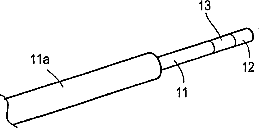
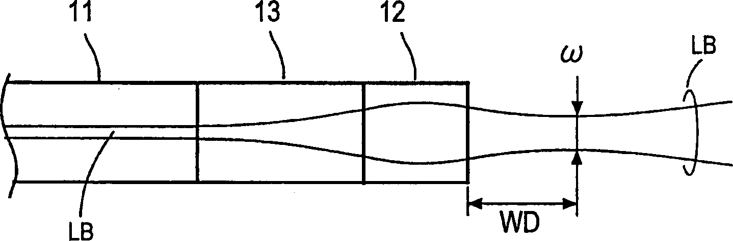
[0024] figure 1 is a perspective view showing a first embodiment of the optical fiber of the present invention, particularly showing its end configuration. The optical fiber of this first embodiment has an end face of a single-mode optical fiber 11 connected to one end face of a short block spacer 13 of a set length having the same refractive index as the core portion, and the other end face of the spacer 13 is connected to a set length of the spacer 13 . The short block-shaped GI fiber (the above-menti...


PUM

PropertyMeasurementUnit
lengthaaaaaaaaaa

Abstract

There are provided an optical fiber having a light focusing function and capable of setting the distance WD to the beam waist position and the beam waist diameter omega independently, and a method of manufacturing the optical fiber efficiently and at high accuracy. An end surface of a single mode optical fiber is connected to one end surface of a very short piece of spacer constituted of an optical fiber the diameter of which is identical to that of the single mode optical fiber and the refractive index of which is uniform. The other end surface of the spacer is connected to one end surface of a very short piece of graded index optical fiber the diameter of which is identical to that of the single mode optical fiber and the refractive index of which varies continuously in the direction of its diameter. The lengths of the spacer and / or the GI fiber can be adjusted to set the beam waist distance WD and the beam waist diameter omega to a proper value suitable for an optical device to be optically coupled to the optical fiber.

Description

technical field [0001] The present invention relates to an optical fiber with a light concentrating function added to the end of an optical fiber connected to an optical device and a manufacturing method thereof, in particular to an optical fiber capable of coupling with a specific optical device with a minimum light loss and its ability to be coupled with a high Efficient and high-precision manufacturing methods for fabricating optical fibers. Background technique [0002] The idea of ​​adding a light concentrating function to the end of an optical fiber connected to a light source, a light receiver, an optical modulator, an optical switch, and other optical devices has been suggested in the past, for example, it is disclosed in JP-A-3-189607 A scheme in which a graded-index optical fiber (hereinafter referred to as GI) in which the refractive index of the core portion changes continuously in the radial direction is connected to one end of a single-...

Claims


Application Information

Patent Timeline
Patent Type & Authority Applications(China)
IPC IPC(8): G02B6/42G02B6/02G02B6/255G02B6/26G02B6/32
CPCG02B6/4249G02B6/2552G02B6/32G02B6/421G02B6/262G02B6/42
Inventor 加藤嘉睦
Owner JAPAN AVIATION ELECTRONICS IND LTD
Why Eureka
Try Eureka