Monitoring system

A technology for monitoring systems and monitoring data, applied in the field of monitoring systems, to solve problems such as troublesome investigations

Inactive Publication Date: 2003-03-19
MITSUBISHI ELECTRIC CORP
View PDF0 Cites 6 Cited by
  • Summary
  • Abstract
  • Description
  • Claims
  • Application Information

AI Technical Summary

Problems solved by technology

In the latter method, it is easier to obtain the information of some monitoring target devices, but generally speaking, when there is an abnormality, it is necessary to obtain the monitoring dat...

Method used


Image

  • Monitoring system
  • Monitoring system
  • Monitoring system

Examples


Embodiment Construction

[0076] Embodiment 1

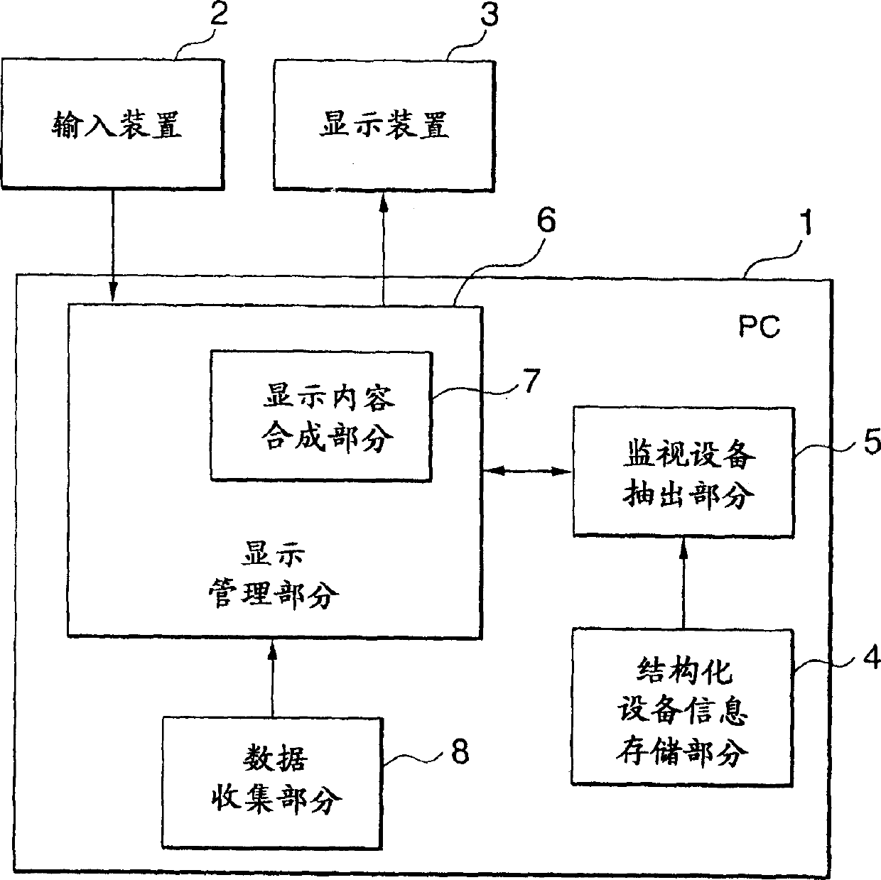
[0077] Fig. 1 is a block diagram showing the configuration of a monitoring system according to the first embodiment. In Fig. 1, 1 is a personal computer body (hereinafter abbreviated as PC) as a data processing device, 2 is an input device connected to the PC, 3 is a display device connected to the PC, and 4 to 8 are included in the PC1. Among the constituent elements, 4 is the structured device information storage part for storing and collecting structured device information, 5 is the monitoring device extraction part, 6 is the display management part, and 7 is the display content synthesis part included in the display management part 6 , 8 is the data collection part.

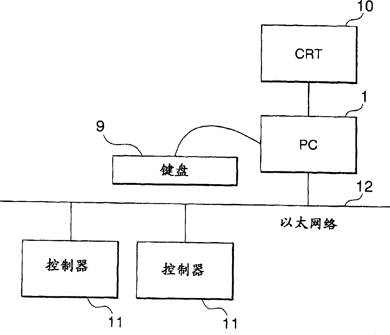
[0078] The overall configuration when this monitoring system is actually used is shown in FIG. 2 , for example. In FIG. 2, a keyboard 9 is provided as the input device 2 in FIG. 1, and a CRT 10 is provided as the display device 3 in FIG. The input device 2 may not be a keyboard, but, ...


PUM


Abstract

A monitoring system indicating the condition of a plant at any time and from any place by particularly utilizing a small graphical content such as the display of a handy cellular phone. In particular, necessary equipment information can be quickly extracted from among many pieces of equipment to be monitored in a large-scale plant including a lot of monitored objects. The monitoring system includes a structured equipment information storage part for storing structured equipment information including equipment information on pieces of equipment and relational information describing relations among the pieces of equipment, and a monitored equipment extraction part for extracting a set of pieces of related equipment information associated with a piece of equipment of interest based on the structured equipment information with the equipment of interest, which is separately designated, being set as a base point of extraction.

Description

technical field [0001] The present invention relates to a monitoring system that collects measurement data and status data of equipment to be monitored and displays the data on a display device, and has a function of effectively displaying the factory status when an abnormality such as a failure occurs on a small screen display device. Background technique [0002] In a monitoring system such as a factory, the measurement data and status data, etc. (monitoring data) of equipment to be monitored are collected and displayed on a display device. When there is an exception, handle the exception according to these displayed contents. However, when the monitored objects are large-scale and there are many monitored objects, it is difficult to display all display contents on one screen. In such a case, conventionally, monitoring information can be grasped by classifying display contents into a plurality of display screens and viewing a desired display screen from among them. [00...

Claims


Application Information

Patent Timeline
IPC IPC(8): G08B21/00G05B23/02G21C17/00
CPCG05B23/0272G21C17/00Y02E30/30
Inventor 北村操代井上胜行小岛泰三
Owner MITSUBISHI ELECTRIC CORP
Why Eureka
Try Eureka