Dynamic split-phase compensation method and device for reactive power

A compensation device and compensation method technology, applied in the direction of reactive power adjustment/elimination/compensation, reactive power compensation, etc., can solve the problems of phase separation, classification, fast and tracking compensation, large impact current, and long switching time and other problems, to achieve the effect of friendly software interface, fast compensation effect, and small maintenance workload

Inactive Publication Date: 2003-03-19
WUHAN UNIV
View PDF0 Cites 17 Cited by
  • Summary
  • Abstract
  • Description
  • Claims
  • Application Information

AI Technical Summary

Problems solved by technology

[0003] At present, most of the low-voltage shunt capacitor banks adopt the delta connection method, and the reactive power compensation is static compensation. The AC contactor is used as the switching actuator of the power capacitor. The impact current is large when it is put in, and overvoltage is generated when it is cut off, and its own contacts are vulnerable. , loud noise or even fusion welding, and long switching time
In the control link, it is basically impossible to meet the requirements of phase separation, classification, fast and tracking compensation

Method used


Image

  • Dynamic split-phase compensation method and device for reactive power
  • Dynamic split-phase compensation method and device for reactive power
  • Dynamic split-phase compensation method and device for reactive power

Examples


Embodiment Construction

[0038] The present invention will be further described below in conjunction with accompanying drawing.

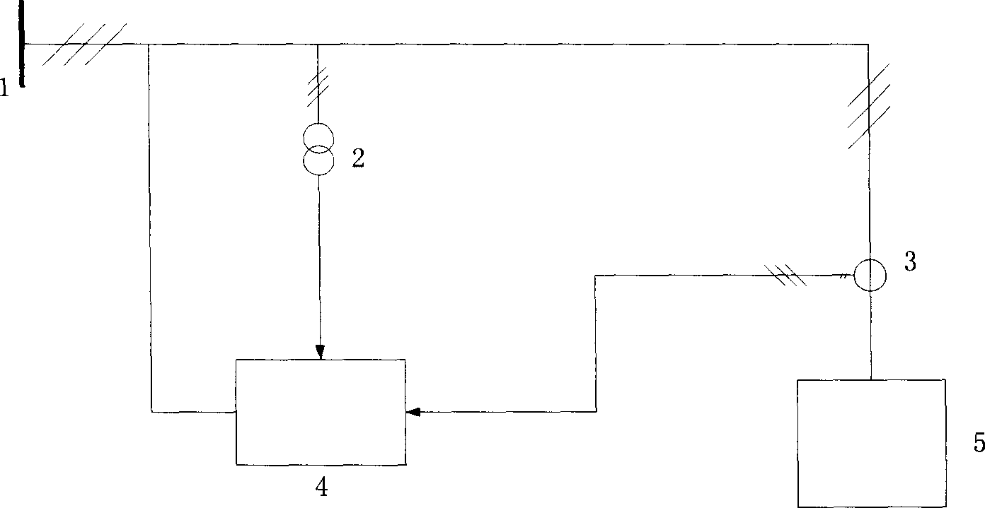
[0039] Such as figure 1 As shown, the voltage and current of bus 1 are converted into standard 100V voltage and standard 1A (5A) current by voltage transformer 2 and current transformer 3, and then sent to dynamic reactive power phase separation compensation device 4. The dynamic reactive power phase-splitting compensation device 4 processes the sampled data, calculates the reactive power to be compensated, and generates a corresponding compensation strategy, puts in or removes capacitor banks of each phase, and performs dynamic reactive power compensation to the load 5 .

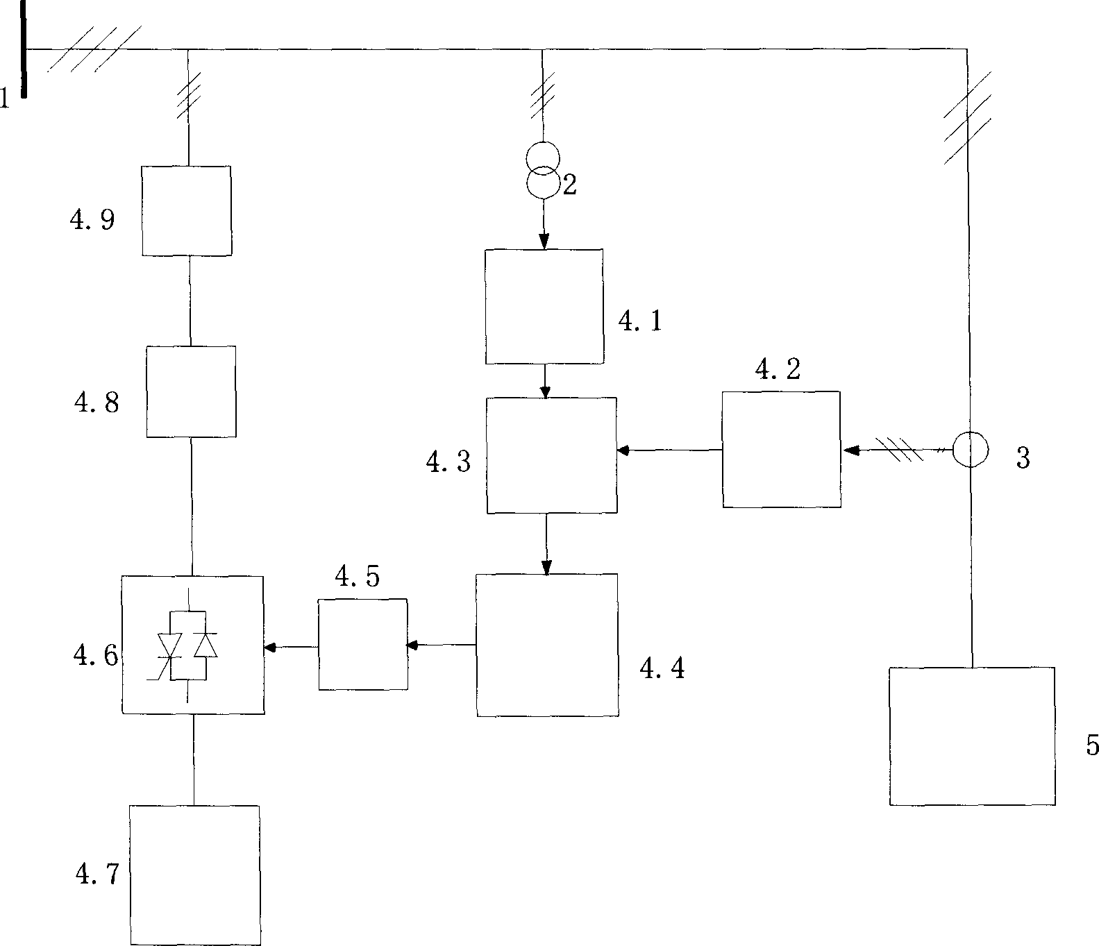
[0040] Such as figure 2 As shown, the working principle of the dynamic reactive power phase-splitting compensation device of the present invention is as follows: the voltage and current signals output by the voltage transformer 2 and the current transformer 3 connected to the bus 1 are passed through t...


PUM


Abstract

The present invention is dynamic split phase compensation method and device of reactive power. Thyristor and diode in inverse parallel connection are used as the switch for compensation capacitor and controlled with industrial PC, and multistage capacitor combination is split phase thrown in and thrown off via tracking the reactive current and reactive power. The capacitors are thrown in while the capacitor voltage is equal to the system voltage and this eliminates the transient course for fast and accurate compensation. The present invention can also compensate unbalanced reactive power. The present invention is correct, practical and effective, and may be used in reactive compensation of power network to raise the power factor of load and electric energy quality.

Description

technical field [0001] The invention belongs to the technical field of power system power quality control, and in particular relates to a dynamic reactive power phase separation compensation method and device. Background technique [0002] In the low-voltage distribution network, switching parallel capacitor banks are widely used for on-site reactive power compensation to reduce reactive power transmission in power transmission, reduce line loss, improve voltage quality, increase active power transmission, and ensure safe and economical operation of the power supply system. [0003] At present, most of the low-voltage shunt capacitor banks adopt the delta connection method, and the reactive power compensation is static compensation. The AC contactor is used as the switching actuator of the power capacitor. The impact current is large when it is put in, and overvoltage is generated when it is cut off, and its own contacts are vulnerable. , loud noise or even fusion welding, a...

Claims


Application Information

Patent Timeline
Patent Type & Authority Applications(China)
IPC IPC(8): H02J3/18
CPCY02E40/30
Inventor 陈允平刘会金彭辉
Owner WUHAN UNIV
Why Eureka
Try Eureka