
Detection apparatus for operation force on operation rod and corresponding displacement

A test device and joystick technology, which is applied to the field of test devices on the joystick, and the test device for the operating force and corresponding displacement on the joystick, which can solve the limitations of the application range, the driver's grip does not meet the requirements, and cannot meet the detection requirements, etc. problem, to achieve the effect of low price and high reliability

Inactive Publication Date: 2003-03-26
SHANGHAI JIAO TONG UNIV
View PDF1 Cites 12 Cited by
  • Summary
  • Abstract
  • Description
  • Claims
  • Application Information

AI Technical Summary

Problems solved by technology

Although this utility model can test the vehicle parking brake control force and the hand pull force of other joysticks, it cannot test the corresponding spatial angular displacement of the joystick, so it cannot meet the new and higher detection requirements for the maneuverability of the vehicle joystick; and The shape of the handle is different from the handle of the actual vehicle joystick, and the driver's grip posture does not conform to the actual manipulation of the human body, so the measured value is different from the control manipulation force when the tester is not installed; The method of measuring the vehicle joystick is installed and fixed, and the adjustment and positioning of the height direction is not convenient enough, so the application range of this technology is greatly limited

Method used


Image

  • Detection apparatus for operation force on operation rod and corresponding displacement
  • Detection apparatus for operation force on operation rod and corresponding displacement
  • Detection apparatus for operation force on operation rod and corresponding displacement

Examples


Embodiment Construction

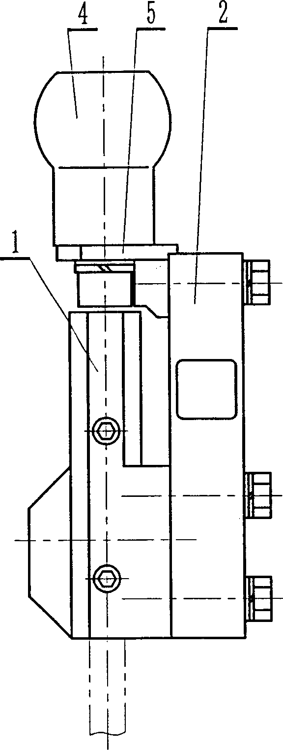
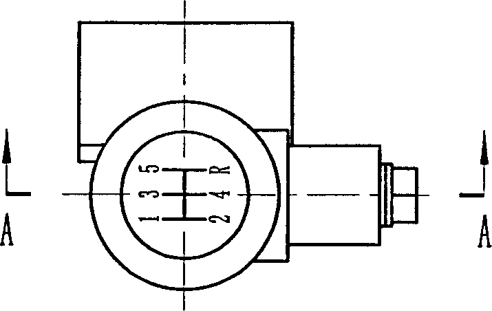
[0010] Such as figure 1, figure 2, Figure 3 and Figure 4 As shown, the present invention mainly includes: joystick base 1, manipulation force sensor 2, inclination displacement sensor 3, joystick handle head 4, handle connecting rod 5, and its connection method is: manipulation force sensor 2 is fixed on joystick base 1 by screws side, the inclination displacement sensor 3 is fixed on the other side of the operating lever base 1 by screws, and the joystick head 4 is fixedly connected with the sensitive part of the operating force sensor 2 through the handle connecting rod 5. During the test, the operating lever base 1 together with The manipulating force sensor 2 and the inclination displacement sensor 3 fixed on it are set on the joystick under test and fastened with screws.

[0011] The joystick seat 1 is a sleeve-shaped structure, and the joystick seat 1 is provided with a hole with the same diameter as the vehicle joystick, and the top of the hole has a step.

[00...


PUM


Abstract

A test device for testing control force on the control lever and corresponding shift comprises control level saet, a control force sensor, tilt angle shift sensor, control level and connecting rod connected in the following way: the control force sensor and corresponding tilt angle shift sensor are fixed at both sides of the control lever seat by screws the control lever fixedly connected with the sensitive part of the control force sensor by screws when testing, the control level seat and the sensor fixed on it are sleeved on the tested control level and fixed by screws.

Description

technical field [0001] The invention relates to a test device on a joystick, in particular to a test device for a manipulation force and a corresponding displacement on a joystick, and belongs to the field of vehicle detection in mechanical engineering. Background technique [0002] The push-pull manipulation force and the corresponding angular displacement of the joystick of the vehicle or some construction machinery are new requirements for the detection of the manipulation performance of the manipulation mechanism. Through synchronous continuous dynamic detection of the driver's push-pull manipulation force and The corresponding relationship of the angular displacement of the joystick is used to judge the correctness of the design of the manipulation mechanism, the quality of assembly, and the wear and tear of the system. At present, an S-shaped resistance strain pull pressure sensor or a beam-type resistance strain hand pull force sensor and the corresponding installatio...

Claims


Application Information

Patent Timeline
IPC IPC(8): G01B7/30G01D5/16G01D21/02G01L5/22
Inventor 程晓鸣黄宏成何维廉赵宇彤
Owner SHANGHAI JIAO TONG UNIV
Learn More