Lay loop current control type double dropping half bridge convertor

A half-bridge inverter and hysteresis current technology, which is applied in the field of hysteresis current-controlled double-buck half-bridge inverters, can solve problems such as affecting system efficiency

Inactive Publication Date: 2003-04-16
NANJING UNIV OF AERONAUTICS & ASTRONAUTICS
View PDF0 Cites 20 Cited by
  • Summary
  • Abstract
  • Description
  • Claims
  • Application Information

AI Technical Summary

Problems solved by technology

But the control method used is based on the slope comparison SPWM. In order to ensure the normal operation of the circuit, the output voltage will

Method used


Image

  • Lay loop current control type double dropping half bridge convertor
  • Lay loop current control type double dropping half bridge convertor
  • Lay loop current control type double dropping half bridge convertor

Examples


Embodiment Construction

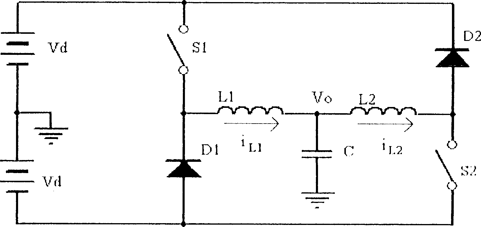
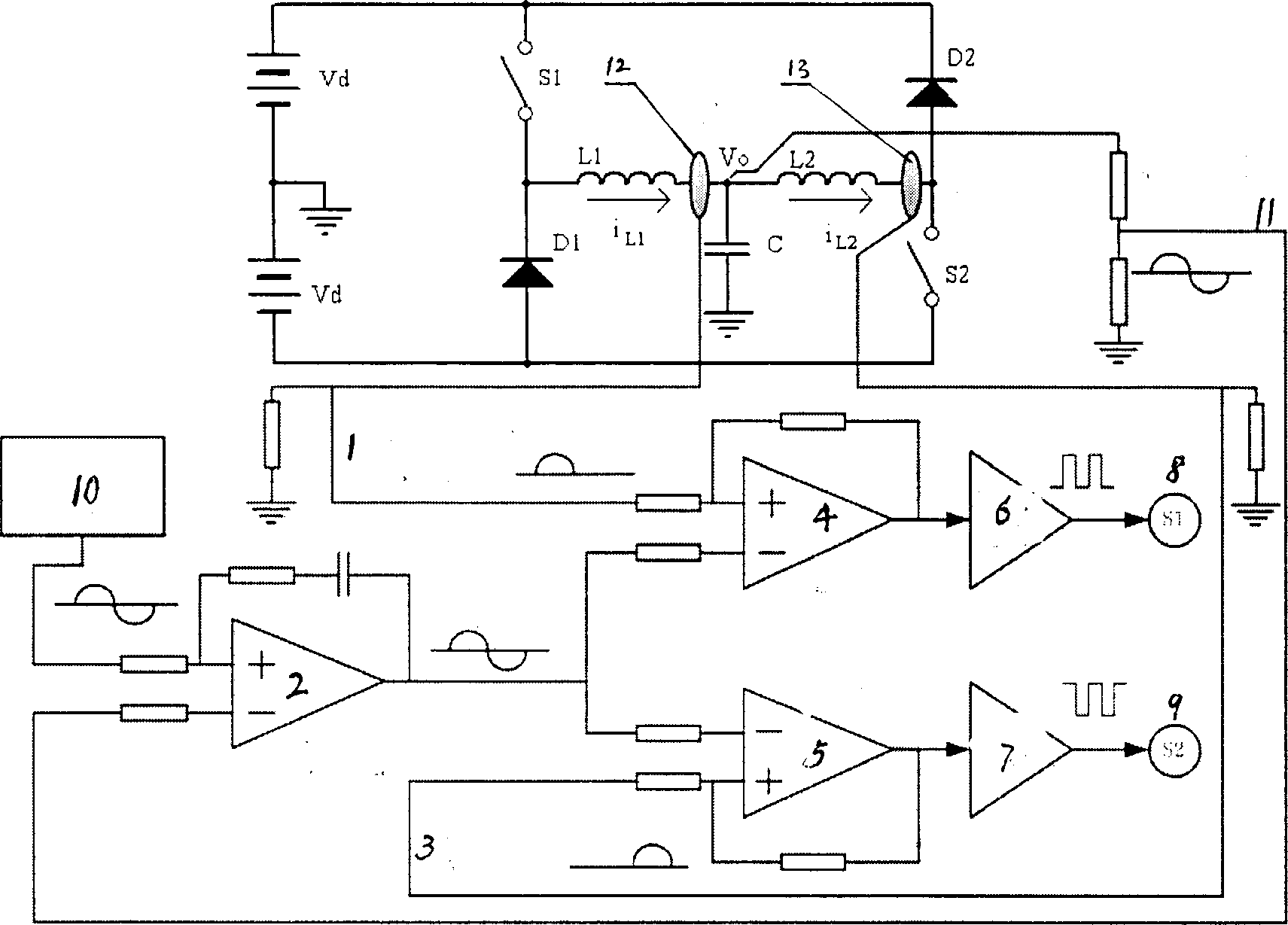
[0012] The specific embodiment of the present invention will be described according to the accompanying drawings. Depend on figure 1 It can be seen that the main circuit of the hysteresis current control type double-buck (BUCK) half-bridge inverter of the present invention is composed of two buck (BUCK) circuits. When the inverter outputs a forward current, the power supply Vd 1 The output positive end is connected to the power switch tube S in turn 1 , filter inductance L 1 , filter capacitor C and its anode and power supply Vd 2 The negative terminal is connected, and the cathode is connected to the power switch tube S 1 with filter inductor L 1 The connection point of the freewheeling diode D 1 The modulation filter output circuit that forms the BUCK circuit; when outputting negative current, the power supply Vd 2 The output negative terminal is connected to the power switch tube S 2 , filter inductance L 2 , filter capacitor C and its anode connected to the power s...


PUM


Abstract

A double dropping voltage half-bridge inverter relates to lag loop current control in which the main circuit is composed of two dropping voltage circuits, namely, power Vd1, power switch tube S1, filter inductor L1, filter capacitor C1 and continuous diode D1 to form a dropping voltage inversion circuit and the other inversion circuit is made up of power Vd2, power switch tube S2, filter inductorL2, filter capacitor C and continuous diode D2 which does not need any biased operation circuit to and reduce conductive loss of main circuit apparatus. Since this circuit applies nonlinear lag loop control and automatically adjust increasing switch frequency to limit high frequency ripple of inductance current in a definite loop width, this invention eliminates output voltage distortion resultedfrom continuous or discontinuous inductance current.

Description

Technical field: [0001] The hysteresis current control type double step-down half-bridge inverter of the invention belongs to the power electronic inverter. Background technique: [0002] With the development of high-frequency power devices, the switching frequency of the inverter has been greatly increased, which reduces the volume and weight of the filter and improves the dynamic response performance. The development of AC power sources such as aviation power supplies, UPS systems, and high-performance motor drives all place higher requirements on the performance of inverters. How to further increase the power density of the converter and how to achieve high frequency while ensuring high efficiency are the key issues of current research. At higher switching frequencies, switching loss is one of the main losses, and soft switching technology can effectively reduce the switching loss of the converter. In the past ten years, scholars at home and abroad have done a lot of re...

Claims


Application Information

Patent Timeline
IPC IPC(8): H02M7/42H02M7/48
Inventor 刘军严仰光王慧贞龚春英
Owner NANJING UNIV OF AERONAUTICS & ASTRONAUTICS
Why Eureka
Try Eureka