Optical communication system
An optical communication system and optical communication module technology, applied in transmission systems, electromagnetic wave transmission systems, optics, etc., can solve problems such as limiting wavelengths and systems, complex optical systems, and increasing costs.
- Summary
- Abstract
- Description
- Claims
- Application Information
AI Technical Summary
Problems solved by technology
Method used
Image
Examples
no. 1 example
[0074]Fig. 5 is a schematic diagram showing an example of a system employing the optical communication system of the present invention. This optical communication system 3 is designed to connect two personal computers (hereinafter referred to as "PC") 15-1 and 15-2 and electronic equipment 16, such as a digital video camera, a digital steel camera, a portable Information terminal, printer or digital TV. PC15-1 has built-in optical communication modules 1-1 and 1-3. The PC 15-2 and the electronic device 16 have built-in optical communication modules 1-2 and 1-4, respectively. The optical communication modules 1-1 and 1-2 use the longer transmission distance optical fiber 2-1 as the transmission medium to perform bidirectional optical communication between PC15-1 and PC15-2. Also, between the PC 15-1 and the electronic device 16, the optical communication modules 1-3 and 1-4 perform bidirectional optical communication using the short transmission distance optical fiber 2-2 as ...
no. 2 example
[0100] Below, refer to Figure 17 A second embodiment of the optical communication system of the present invention is described. Figure 17 In , components with the same or similar functions as those in FIG. 5 are denoted by the same numerals and will not be described again.
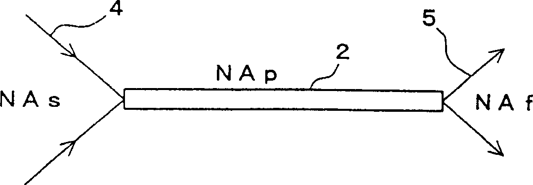
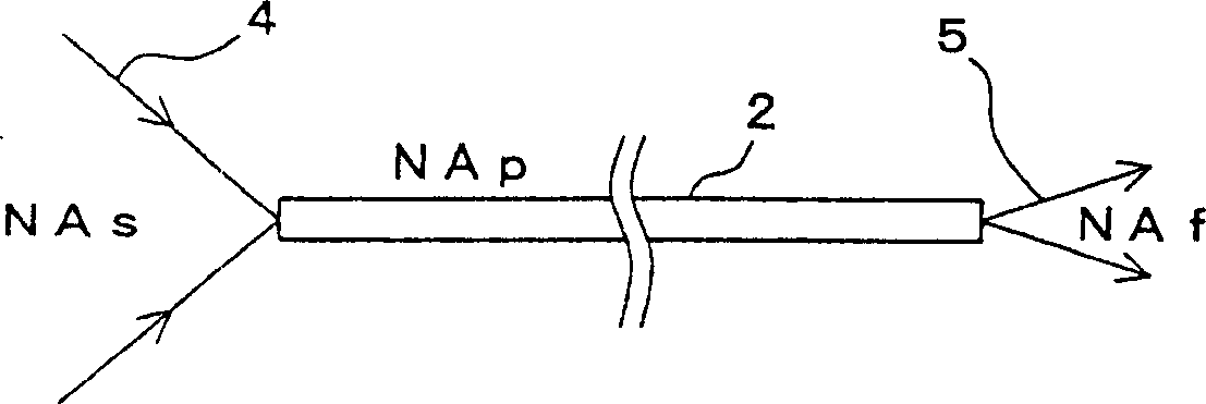
[0101] In the first embodiment, the optical fibers 2-1 and 2-2 have the same numerical aperture NAp (that is, the optical fiber 2 having the same characteristics irrespective of the difference in transmission distance is used). In contrast, in the second embodiment, optical fibers 2-3 and 2-4 having different numerical apertures NAp1 and NAp2 depending on the transmission distance are used.
[0102] In the second embodiment, the numerical aperture NAf of the received light does not change with the numerical aperture NAs of the emitted light and the numerical aperture NAp of the optical fiber 2, but the optical fibers 2 (2-3 and 2 -4).
[0103] As described above, the numerical aperture NAf of the rece...
no. 3 example
[0107] Below, refer to Figure 18 and 19 A third embodiment of the optical communication system of the present invention is described. Figure 18 and 19 In , components with the same or similar functions as those in the first and second embodiments are denoted by the same reference numerals and will not be described again.
[0108] The present embodiment focuses on an optical communication system suitable for coexistence of optical communication modules 1 of different communication speeds or different optical characteristics. As an example, discuss Figure 18 Shown is an optical communication system 3 in which two optical fibers 2 (2A, 2B) are used to provide bidirectional optical communication. Optical communication is provided between the first optical communication module 1A and the second optical communication module 1B using the optical fiber 2 (2A, 2B) as a transmission medium. The optical fiber 2A is used for transmission from the first optical communication module...
PUM
 Abstract
Description
Claims
Application Information
 - R&D
- Intellectual Property
- Life Sciences
- Materials
- Tech Scout
- Unparalleled Data Quality
- Higher Quality Content
- 60% Fewer Hallucinations
Browse by: Latest US Patents, China's latest patents, Technical Efficacy Thesaurus, Application Domain, Technology Topic, Popular Technical Reports.
© 2025 PatSnap. All rights reserved.Legal|Privacy policy|Modern Slavery Act Transparency Statement|Sitemap|About US| Contact US: help@patsnap.com


