
Dispersion compensated optical fibre and dispersion compensated optical fibre module

A dispersion compensating optical fiber and dispersion technology, which is applied in the direction of required dispersion optical fiber, clad optical fiber, multi-layer core/clad optical fiber, etc., which can solve the problems of transmission characteristic degradation, large transmission loss, etc.

Inactive Publication Date: 2003-04-30
FUJIKURA LTD
View PDF2 Cites 12 Cited by
  • Summary
  • Abstract
  • Description
  • Claims
  • Application Information

AI Technical Summary

Problems solved by technology

As a result, further dispersion compensation is required in order to realize high-speed transmission; however, transmission characteristics may be deteriorated due to large transmission loss

Method used


Image

  • Dispersion compensated optical fibre and dispersion compensated optical fibre module
  • Dispersion compensated optical fibre and dispersion compensated optical fibre module
  • Dispersion compensated optical fibre and dispersion compensated optical fibre module

Examples


Embodiment Construction

[0038] Preferred embodiments of the present invention will be explained with reference to the accompanying diagrams.

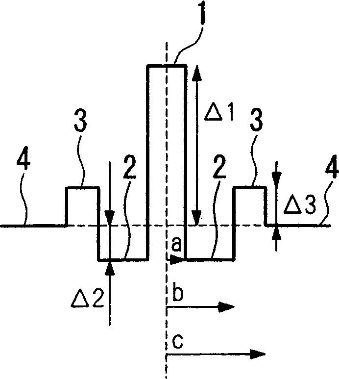
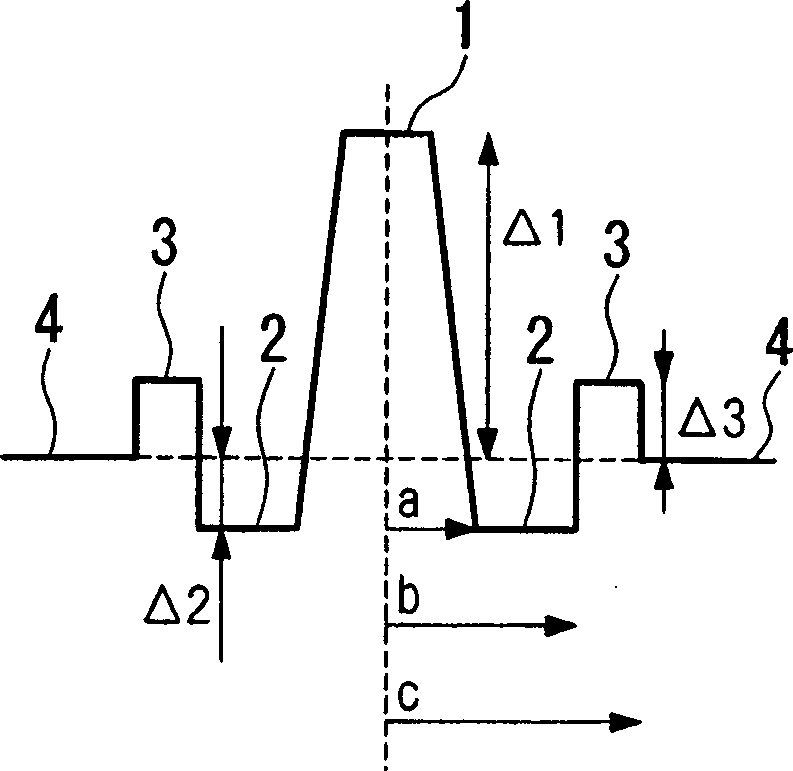
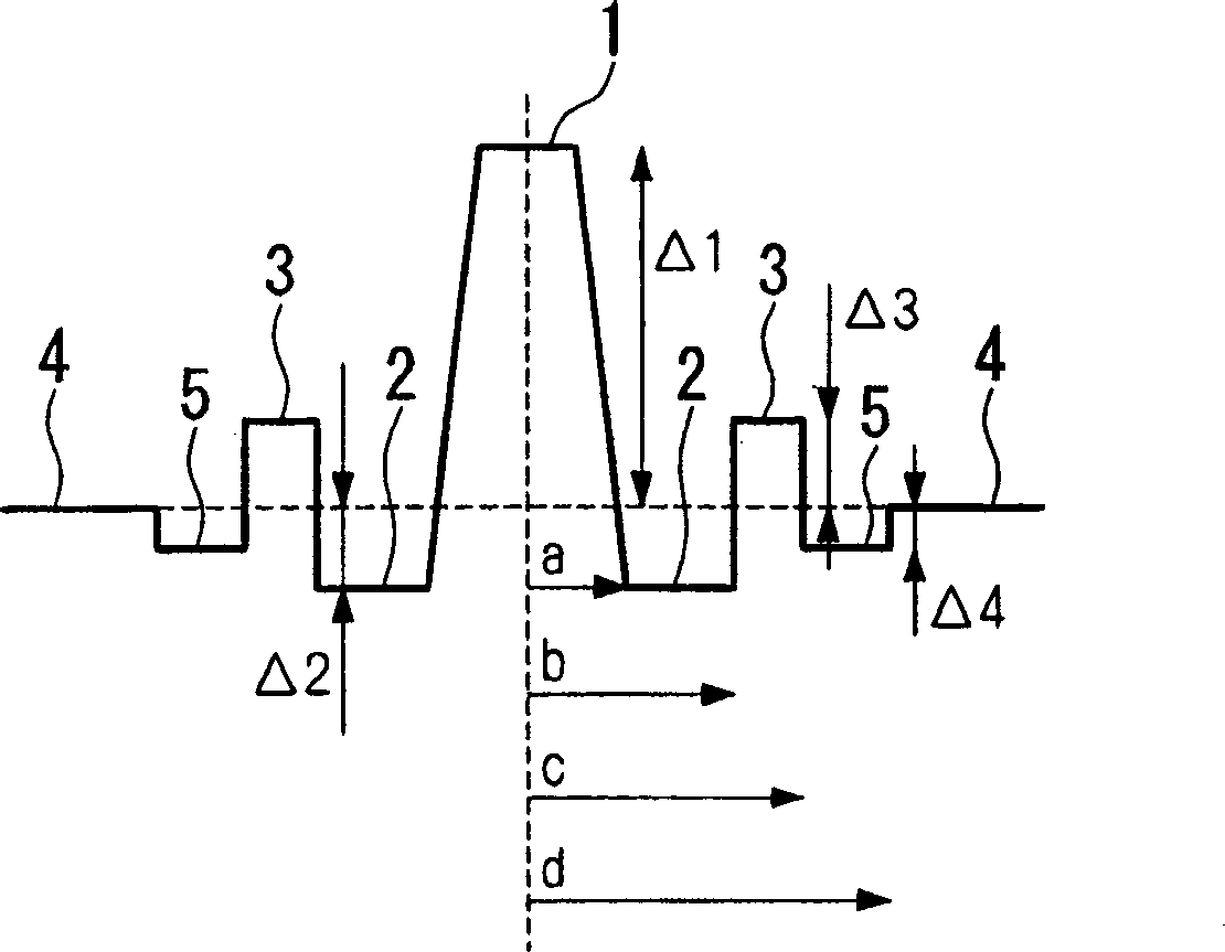
[0039] Figures 1A to 1C The refractive index profile of the dispersion compensating fiber according to the present invention is shown.

[0040] exist Figures 1A to 1C , reference numeral 1 designates a central core area, reference numeral 2 designates an indentation area located around the central core area 1, reference numeral 3 indicates an annular core area located around the indentation area 2, and reference numeral 4 indicates an annular core area located around the annular core area 3 cladding.

[0041] exist Figures 1A to 1C , reference symbol "a" indicates the radius of the central core 1, reference symbol "b" indicates the radius of the press core 2, reference symbol "c" indicates the radius of the annular core 3, and reference symbol Δ1 indicates the radius of the central core 1 relative to the cladding 4 , the reference symbol Δ2 indicates the r...


PUM


Abstract

A dispersion compensating fiber, which has a negative dispersion slope with a large absolute value while maintaining the absolute value of the chromatic dispersion, and which has sufficient dispersion slope compensation properties even for the non-zero dispersion shifted optical fiber requiring a large RDS for dispersion compensation. In this dispersion compensating fiber, the radius of a ring core region (3) is set in a range from 6.7 mu m to 10.7 mu m, the radius ratio of a depressed core region (2) relative to a central core region (1) is set in a range from 2.0 to 3.0, and the radius ratio of the ring core region (3) relative to the depressed core region (2) is set in a range from 1.3 to 2.0, the relative refractive index difference of the central core region (1) relative to the cladding (4) is set in a range from +1.00% to +1.80%, the relative refractive index difference of the depressed core region (2) relative to the cladding (4) is set in a range from -1.20% to -1.50%, and the relative refractive index difference of the ring core region (3) relative to the cladding (4) is set in a range from +0.20% to +0.50%.

Description

technical field [0001] The present invention is related to dispersion compensating fiber and dispersion compensating fiber module, and in particular to a dispersion compensating fiber and a dispersion compensating fiber for compensating dispersion in a non-zero dispersion-shifted fiber having a dispersion of about several ps / nm / km in the 1.55 μm band Fiber optic module. Background technique [0002] As erbium-doped fiber amplifiers have become available, in particular, communication systems using the 1.53-1.63 μm band, such as ultra-long-distance non-regenerative relay systems using optical amplifiers, have been commercialized. On the other hand, with the demand for increased transmission capacity, wavelength division multiplexing transmission technology has been rapidly developed, and some transmission paths installed for this purpose have been commercialized. In recent technology trends, expanding the operating wavelength band and increasing wavelength diversity will be r...

Claims


Application Information

Patent Timeline
Patent Type & Authority Applications(China)
IPC IPC(8): G02B6/036
CPCG02B6/0228G02B6/03666G02B6/02261G02B6/03644
Inventor 爱川和彦清水正砂铃木孝昭铃木龙次中山真一姬野邦治
Owner FUJIKURA LTD
Learn More