Magnetic sensor

A magnetic sensor and magnetic field technology, applied in the field of magnetic sensors, can solve problems such as difficulty in forming a bias magnetic field, high power consumption of the bias magnetic field, and large area occupied by the coil 110

Inactive Publication Date: 2003-05-14
YAMAHA CORP
View PDF0 Cites 27 Cited by
  • Summary
  • Abstract
  • Description
  • Claims
  • Application Information

AI Technical Summary

Problems solved by technology

[0003] However, according to the above-mentioned prior art, there are many parts of the coil 110 that do not directly form the above-mentioned bias magnetic field, so that the occupied area of ​​the coil 110 is large, so the coil 110 becomes an obstacle to miniaturization of the magnetic sensor.
In addition

Method used


Image

  • Magnetic sensor
  • Magnetic sensor
  • Magnetic sensor

Examples


Embodiment Construction

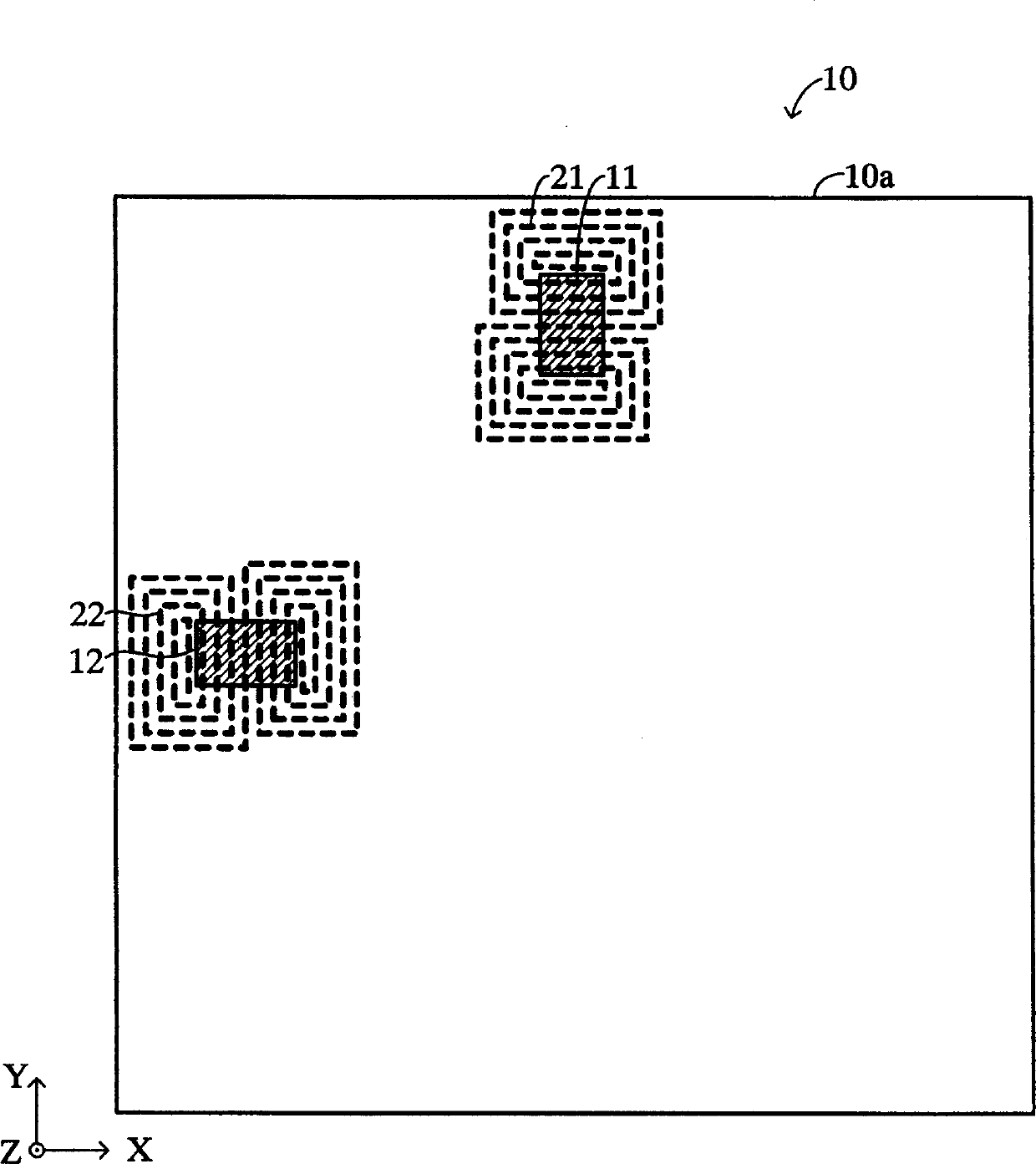
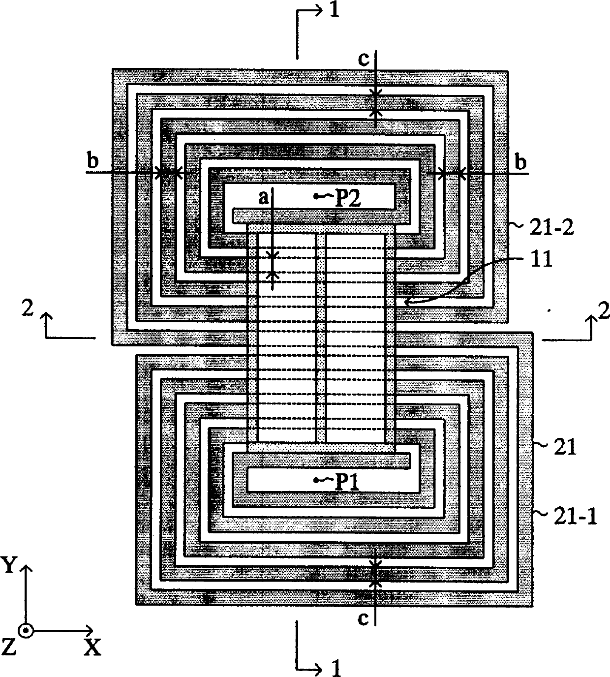
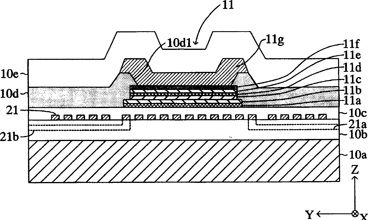
[0065] Embodiments of the magnetic sensor according to the present invention will be described below with reference to the drawings. rough floor plan figure 1 The shown magnetic sensor 10 according to the first embodiment is made, for example, of SiO 2 / Si, Si 3 N 4 / Si, glass or quartz, is provided with a substrate 10a having a square side along the X-axis and Y-axis perpendicular to each other and having a thickness in the Z-axis direction perpendicular to the X-axis and the Y-axis, two film-shaped The magnetic tunnel effect elements (groups) 11, 12 provide bias magnetic fields for detecting an external magnetic field (measurement) to the magnetic tunnel effect elements 11, 12 respectively, and place them under the magnetic tunnel effect elements (groups) 11, 12 (substrates) respectively. The bias magnetic field coils 21 and 22 are formed on the 10a side, that is, the side in the negative direction of the Z-axis) parallel to the film plane of the above-mentioned thin fil...


PUM


Abstract

The present invention provides a magnetic sensor having a space-saving coil of low power consumption for generating a bias magnetic field applied to a magnetoresistive effect element. A magnetic sensor comprises a thin-film-like magnetic tunnel effect element (magnetoresistive effect element) 11. A coil 21 is disposed in a plane under the magnetic tunnel effect element 11 and parallel to a thin-planar film surface of the element. The coil 21 is a double spiral type coil which includes a first spiral conductor portion 21-1 and a second spiral conductor portion 21-2. The magnetic tunnel effect element 11 is disposed between a spiral center P1 of the first conductor portion 21-1 and a spiral center P2 of the second conductor portion 21-2 in a plan view. The first and second conductor portions 21-1 and 21-2 are connected such that electric currents in the same direction pass through a part of the first conductor portion 21-1 that overlaps the magnetic tunnel effect element 11 in a plan view and through a part of the second conductor portion 21-2 that overlaps the magnetic tunnel effect element 11 in a plan view.

Description

technical field [0001] The present invention relates to a magnetic sensor provided with a magnetoresistance effect element and a coil for generating a magnetic field applied to the magnetoresistance effect element. Background technique [0002] Heretofore, a magnetic sensor using a magnetoresistance effect element such as a giant magnetoresistance effect element (GMR element) or a magnetic tunnel effect element (TMR element) as a magnetic field detection element is known. Such as Figure 33 As shown, such a magnetic sensor is provided with a coil 110 for applying a bias magnetic field to the magnetoresistance effect element 100 . In this case, the coil 110 is formed in a spiral shape, and the magnetoresistance effect element 100 is formed above the spiral circumference of the coil 110 . The current flowing through the wires of the coil 110 directly below the magnetoresistance effect element 100 generates a bias magnetic field for the magnetoresistance effect element 100 . ...

Claims


Application Information

Patent Timeline
IPC IPC(8): G01R33/09H01L43/08
CPCG01R33/093B82Y25/00H10N50/10
Inventor 铃木利尚佐藤秀树金子诚
Owner YAMAHA CORP
Why Eureka
Try Eureka