Modular stator structure

A technology of stator and iron core blocks, applied in the field of modular stator structure, can solve the problems of high cost, waste of resources, and unusable equipment

Inactive Publication Date: 2003-05-14
范家豪 +1
View PDF0 Cites 5 Cited by
  • Summary
  • Abstract
  • Description
  • Claims
  • Application Information

AI Technical Summary

Problems solved by technology

However, the above-mentioned known stator already has a predetermined number of poles after it is manufactured. If you want to increase or decrease the number of poles, you must open the mold again, which makes the manufacturer expensive and inflexible, and the original equipment cannot be used, resulting in waste of resources and Increase design and manufacturing costs

Method used


Image

  • Modular stator structure
  • Modular stator structure
  • Modular stator structure

Examples


Embodiment Construction

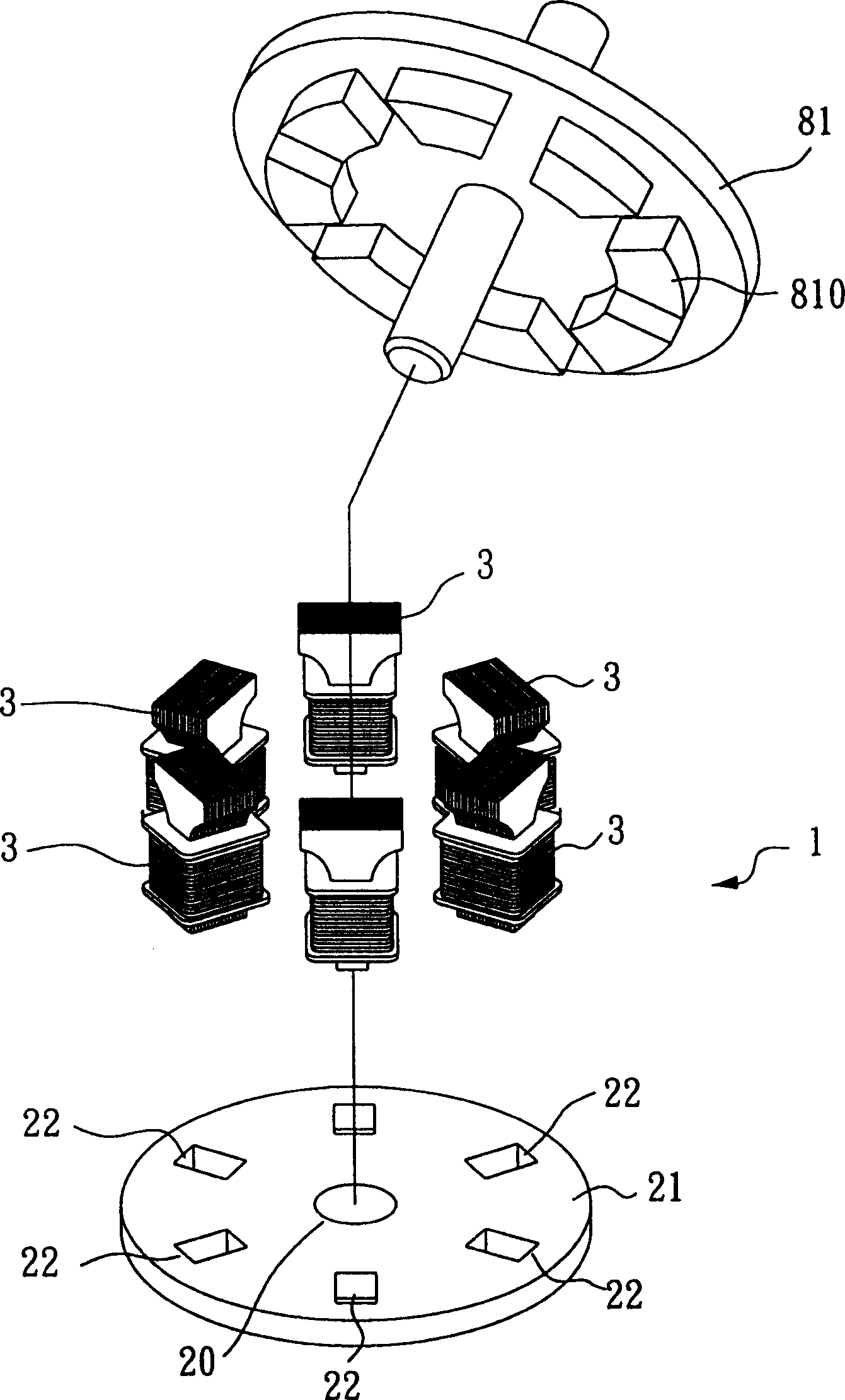
[0031] Regarding the first preferred embodiment of the modular stator structure of the present invention, the stator structure of an electric motor (motor) is used as an example to illustrate, please refer to figure 1 The three-dimensional exploded view shown is mainly composed of the base 21 and six core modules 3 .

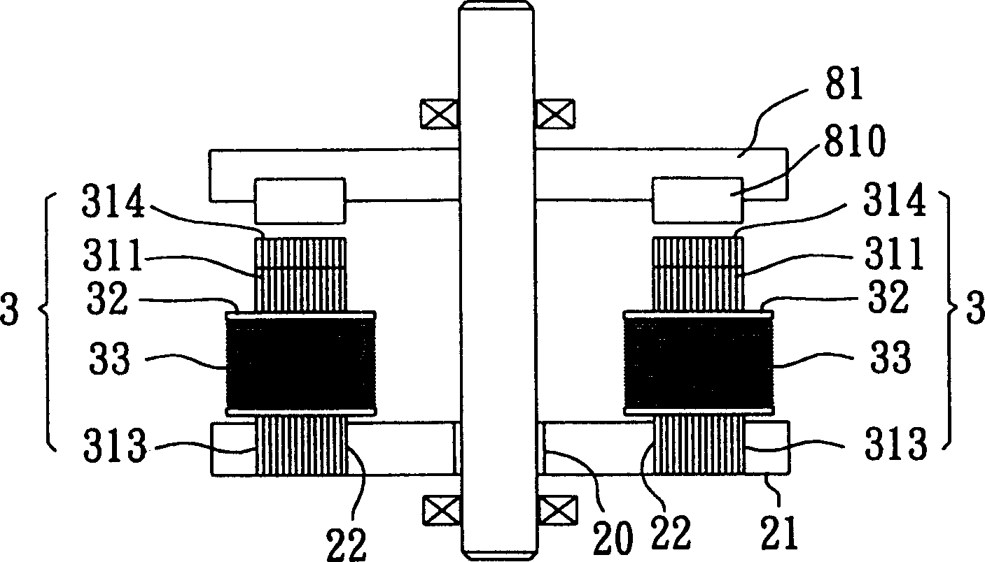
[0032] The aforementioned base 21 is made of magnetically permeable materials such as iron and steel, and is in the shape of a disk. Six fixing grooves 22 are recessed on the surface of the base 21 along an annular interval. The six iron core modules 3 respectively correspond to the six fixing slots 22 assembled on the surface of the base 21 , and the base 21 can be matched with the rotor 81 to form a motor.

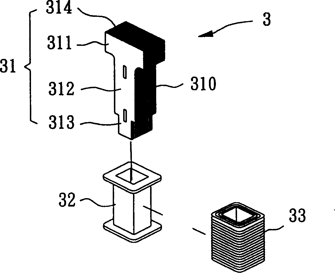
[0033] figure 2 It is a detailed exploded view showing the aforementioned iron core module 3 , and the iron core module 3 is composed of an iron core block 31 , an insulating bushing 32 , and a coil 33 . In this example, the iron core block 31 is formed...


PUM


Abstract

The modular stator structure includes base seat of magnetically conducting material and several iron core modules. The iron core modules are corresponding to the fixing notches in the base seat. Eachiron module includes one iron block of magnetically conducting material, one insualting lining and one winding. Several iron modules may be combined flexibly on the base seat to form different combination and may be installed fast onto the based seat in relatively lower design and manufacture cost.

Description

technical field [0001] The invention relates to a modular stator structure, in particular to a stator structure commonly used in electric motors or generators. Background technique [0002] The stator structure of the known electric motor or generator is designed with the required number of poles according to the required capacity and rotational speed, and manufactured according to the required number of poles. The traditional stator with a predetermined number of poles is formed by casting, or by stacking iron chips (or silicon steel sheets) with a thickness of about 0.5mm-0.35mm and then riveting. However, the above-mentioned known stator already has a predetermined number of poles after it is manufactured. If you want to increase or decrease the number of poles, you must open the mold again, which makes the manufacturer expensive and inflexible, and the original equipment cannot be used, resulting in waste of resources and Increase design and manufacturing costs. Conte...

Claims


Application Information

Patent Timeline
IPC IPC(8): H02K1/12
Inventor 范家豪范瑜芳
Owner 范家豪
Why Eureka
Try Eureka