Diode circuit

A technology of diodes and circuits, applied in the field of semiconductor integrated circuits

Inactive Publication Date: 2003-05-28
SEIKO INSTR INC
View PDF0 Cites 13 Cited by
  • Summary
  • Abstract
  • Description
  • Claims
  • Application Information

AI Technical Summary

Problems solved by technology

However, since no current flows if the voltage Vf is not appli

Method used


Image

  • Diode circuit
  • Diode circuit
  • Diode circuit

Examples


no. 1 example

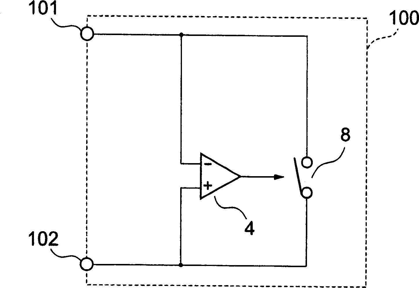
[0030] Figure 4 A specific structural example showing an example of the diode circuit according to the first embodiment of the present invention.

[0031] refer to Figure 4 , which is an n-channel MOS transistor 2 which is a switching element, is arranged between the cathode terminal 101 and the anode terminal 102 of the diode circuit 100 . The source and substrate terminals of n-channel MOS transistor 2 are connected to anode terminal 102 , and the drain terminal thereof is connected to cathode terminal 101 . Furthermore, the cathode of diode 1 is connected to cathode terminal 101 , while the anode terminal of diode 1 is connected to anode terminal 102 . Likewise, the normal input terminal of the second voltage comparator 5 is connected to the anode terminal 102 , while the inverting input terminal of the second voltage comparator 5 is connected to the positive terminal of the first voltage source 10 . Furthermore, the negative terminal of the first voltage source 10 is ...


PUM


Abstract

Provided is a diode circuit with small power consumption. A first voltage comparator (4) compares a voltage at a cathode terminal (101) with a sum of a voltage at an anode terminal (102) and a voltage across a first voltage source (10) to output a reset signal, and a second voltage comparator (5) compares a voltage at the anode terminal (102) with a sum of a voltage at the cathode terminal (101) and a voltage across the second voltage source (11) to output a set signal. A first latch circuit (20) outputs an L signal when the reset signal from the first voltage comparator (4) is inputted, and outputs an H signal when the set signal from the second voltage comparator (5) is inputted. An n-channel MOS transistor (2) turns off upon receiving the L signal, and turns on upon receiving the H signal, to thereby limit an output current.

Description

technical field [0001] The present invention relates to a semiconductor integrated circuit, and more particularly to a diode circuit. Background technique [0002] Diodes have always been used as rectifiers that rectify the direction of current flow into one direction. [0003] figure 2 A diagram showing the voltage between the anode and cathode of a single diode and the current flowing therebetween. The following will refer to figure 2 Describe the operation of a diode stand-alone. [0004] In the case where the voltage between the anode and cathode is negative, i.e. the anode voltage is lower than the cathode voltage, ideally no current flows in the diode. [0005] Likewise, in the case where the voltage between the anode and the cathode is positive, that is, the anode voltage is higher than the cathode voltage, and the voltage between the anode and the cathode is Vf or higher, current flows from the anode to the cathode into the diode. [0006] Ideally, a diode must ...

Claims


Application Information

Patent Timeline
IPC IPC(8): H02J7/06H03K17/06H03K17/30
CPCH03K17/302H03K17/063H03K2017/307H02J7/06
Inventor 中下贵雄
Owner SEIKO INSTR INC
Why Eureka
Try Eureka