

Method for blasting and finishing mould
A finishing and mold wall technology, applied in the direction of casting mold, core, casting mold composition, etc., can solve the problems of time-consuming and expensive, and achieve the effect of simplifying production, simplifying manufacturing and finishing
Inactive Publication Date: 2003-06-11
KME GERMANY GMBH & CO KG
View PDF0 Cites 0 Cited by
- Summary
- Abstract
- Description
- Claims
- Application Information
AI Technical Summary
Problems solved by technology
Not only its manufacture, but also its installation and disassembly into the hole is quite time-consuming and expensive.
Method used
View moreImage
Smart ImageViewing Examples

Examples
Embodiment Construction
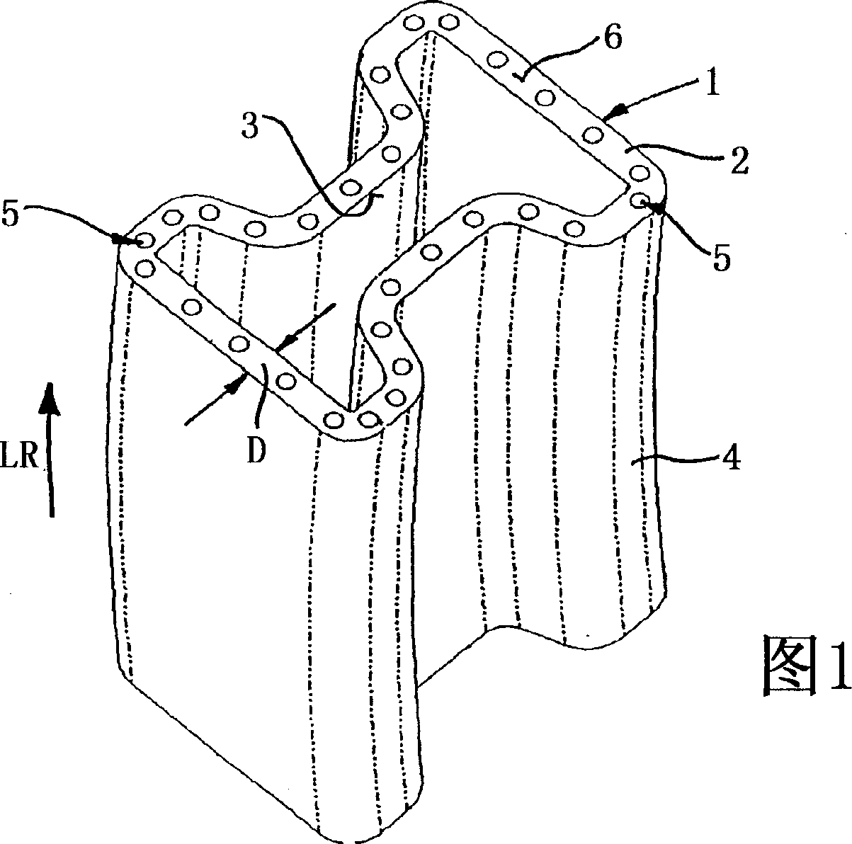
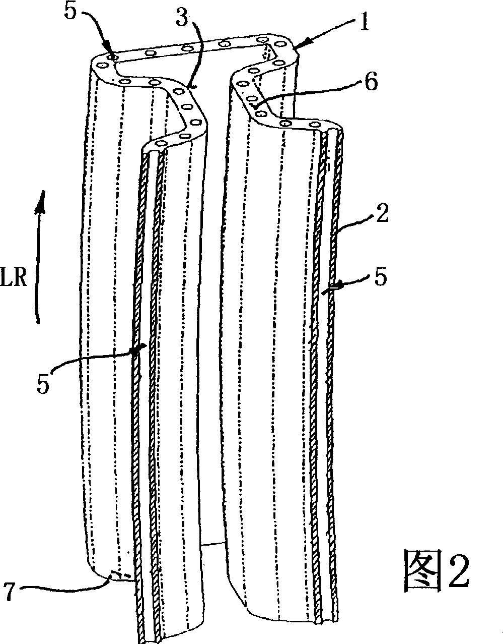
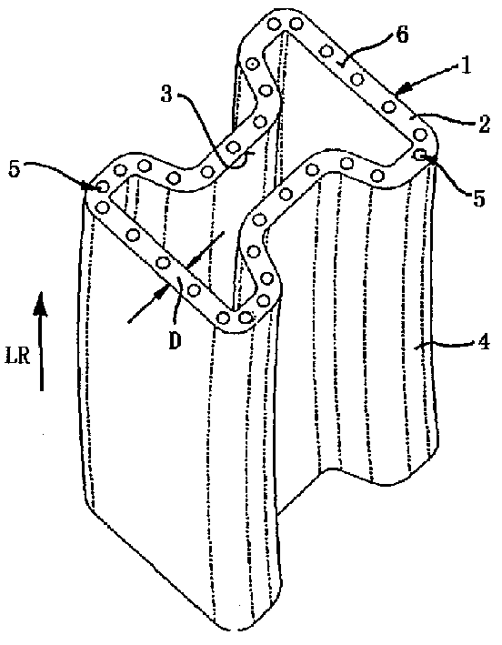
[0020] The tubular form 1 shown in accompanying drawing 1 and accompanying drawing 2 has the cross-section of an I-shaped molding.
[0021] It has a surrounding tubular wall 2 of constant thickness D. The mold given by the inner wall 3 of the tubular form 1 is thus also reflected on the outer surface 4 .
[0022] The holes 5 in the tube wall 2 are distributed along the longitudinal direction of the tube form 1 . The bores 5 run parallel to one another at a distance and emerge from the end faces 6 , 7 of the tube wall 2 . These holes 5 have a circular cross section.
Login to View More PUM
 Abstract
A method for blasting calibrating a chill mold (1) is provided. A calibrating mandrel is inserted into chill mold (1), thereafter an explosive material is placed on the outer surface (4) of chill mold (1) and is ignited. The inner side (3) of chill mold (1) is pressed against the calibrating mandrel by the explosive force, and brought to the setpoint measure. In the mold wall (2), chill mold (1) has bores (5) for cooling means and for measuring elements, which extend in the longitudinal direction (LR) of chill mold (1) and exit at the end faces (6, 7) of mold wall (2). Before the blasting calibration, the bores (5) are filled up with a free-flowing material and tightly closed. The free-flowing material is preferably an incompressible fluid and / or a bulk material.
Description
technical field [0001] The invention relates to a method for explosive finishing of molds having the features stated in the preamble of claim 1 . Background technique [0002] Cooled ingot molds are known in the prior art, in the tube wall of which molds are provided parallel to the longitudinal axis with cooling channels into which coolant can be injected. [0003] Furthermore, tubular molds and ingot molds are known which are provided with vertical and / or horizontal channels in the mold wall in which temperature measuring elements can be installed. [0004] Since the mold is worn during casting, it needs to be stopped and refinished after being put into use for a certain period of time. For this purpose, each pattern is first dechromed and then polished. Next, insert a calibration mandrel whose outer diameter is equivalent to the inner diameter of a new mold in the mold. After inserting the alignment mandrel, the end faces of the form are hermetically closed with plates...
Claims
Login to View More Application Information
Patent Timeline
 Patent Type & AuthorityApplications(China)
IPC IPC(8): B22C9/12B21D3/00B21D3/14B21D26/08B22D7/06B22D11/057
CPCB22D11/057B21D26/08B22C9/12
Inventor罗兰·奥里
OwnerKME GERMANY GMBH & CO KG