
High-efficiency power modulators

A technology of power modulation and power amplifier, which is applied in the direction of power amplifier, modulation, improved amplifier to improve efficiency, etc., and can solve the problem of limiting modulation bandwidth and so on

Inactive Publication Date: 2003-06-11
PANASONIC CORP
View PDF3 Cites 1 Cited by
  • Summary
  • Abstract
  • Description
  • Claims
  • Application Information

AI Technical Summary

Problems solved by technology

Loop dynamics limit the achievable modulation bandwidth when using any feedback control loop

Method used


Image

  • High-efficiency power modulators
  • High-efficiency power modulators
  • High-efficiency power modulators

Examples


Embodiment Construction

[0027] The basis of the invention is linearization for the stated purpose, the standard structure of FIG. 1 is not sufficient. Rather the PA needs to be included as an essential part of the modulator. This means that not only is the modulated signal present at the PA output in the first place at the desired full transmit power, but the PA must actually implement partial modulation.

[0028] To get to this point, it's important to know that any PA is actually a three-port device, with 2 input ports and 1 output port. In the representation amplifier 800's Figure 8 This new PA working mode is drawn in . Each input port has its own transfer function to output port 305 . Further, the two transfer functions can be correlated or independent, depending on the design level of the power amplifier.

[0029] For example, with a PA of linearity class A, there is a very weak relationship between the power supply port and the output signal port, while the relationship between the value a...


PUM


Abstract

The present invention, generally speaking, incorporates the power amplifier as a fundamental constituent of a modulator, using polar modulation techniques. Thus, it is possible to achieve the combination of precision signal generation (including envelope variations) along with high energy efficiency in combinations not possible heretofore. In accordance with one embodiment of the invention, a modulated radio (passband) signal generator produces high quality signals of general type, which specifically includes signals with varying envelopes. Signals are generated with high energy efficiency in the conversion of applied DC power to output RF signal power. The result is longer battery life for products such as mobile phone handsets. Dramatically improved efficiency also allows for a dramatic reduction (10 to 1 or greater) in the size of any required heatsink for the radio transmitter, which significantly lowers both cost and size. Furthermore, continuous operation of these radio transmitters is made possible with small temperature rises using small heatsinks, or even without any heatsink components. This provides for high operating reliability, as well as for greater throughput due to the longer operating time allowed. Another aspect of the invention allows the generation of high quality signals with wide bandwidth, without the need for continuous feedback during operation. This further reduces costs by greatly simplifying the design, manufacturing, and complexity of the transmitter circuitry.

Description

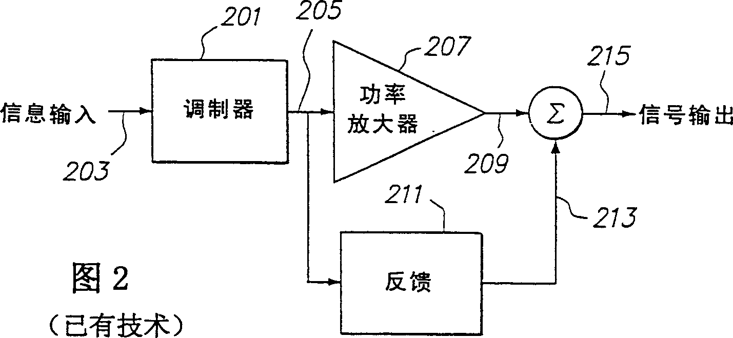
technical field [0001] The present invention relates to radio frequency (RF) power amplifiers. Background technique [0002] In the field of RF communications, with the ever-increasing desire and demand for greater transmission throughput, prioritized signals must exhibit high data efficiency. In general, high data-efficiency signals exhibit envelope-varying characteristics. Such envelope varying signals generally require linear circuit operation. [0003] In a conventional radio transmitter, the modulator and power amplifier (PA) work separately, as shown in Figure 1. Modulator 101 transforms the information input signal 103 to the transmitter into a bandpass signal 105, usually at radio frequency, which can have either a constant envelope (average signal power equal to peak signal power) or a varying envelope (average signal power is less than the peak signal power). The band pass signal 105 is applied to a power amplifier (PA) 107 which produces an output signal 109 w...

Claims


Application Information

Patent Timeline
IPC IPC(8): H03F3/24H03F1/00H03F1/02H03F1/32H03F3/387H04L27/20H04L27/36
CPCH03F1/0211H03F1/3288H03F2200/207H03F1/3282H03F1/3247H03C5/00H03F2200/504H03F2200/324H03F2200/451H03F1/32
Inventor 小伊尔·W·迈克库恩温德尔·B·桑德尔
Owner PANASONIC CORP
Learn More