Low stressed self anchoring method for group anchor steel tension cables

A steel strand, low-stress technology, applied in the direction of cable-stayed bridges, bridge parts, bridge forms, etc., can solve the problems of heavy lifting equipment, high brittleness, low safety reserve, etc., and achieve effective anchorage area increase and fatigue resistance performance Improvement, fatigue performance improvement effect

Inactive Publication Date: 2003-06-18
柳州市威尔姆预应力有限公司
View PDF0 Cites 16 Cited by
  • Summary
  • Abstract
  • Description
  • Claims
  • Application Information

AI Technical Summary

Problems solved by technology

Because the hardness of the carburized layer reaches HRC62, it is very brittle and basically has no plasticity; at the same time, the lateral stress of the anchor plate on the clip cannot be effectively applied, so it is easy to occur: the clip is not firmly anchored, and the steel strand and the clip are easily Slip and other phenomena
[0005] 3. The effective length of the anchoring steel strand of the clip is short, and the safety reserve is low, and the clips follow the processing technology of conventional group anchors. After the clips are closed, they form an ellipse, so that the contact between the clip and the taper hole of the anchor plate is Point-to-surface contact, which is not conducive to the follow-up of the clip and the transmission of radial force
[0006] 4. The weak link of the cable should be at the anchorage point, and the anchorage that relies on high strength, fatigue resistance and high anchorage performance should bear the load as the design focus of the anchorage; and the current market uses group anchor cables because it cannot solve the problem of clamping. The low-stress self-anchoring and fatigue resistance performance of the sheet depends on the bonding force generated by the working section of the steel strand wrapped with epoxy mortar poured into the support cylinder to bear part of the load and improve the fatigue resistance. If the slurry is not dense If there are air holes, it is difficult to ensure safety, and it is difficult to ensure that the slurry will not crack when it is resistant to fatigue for a long time, so that the grip will fail
The national standard "GB / T14370-2000" stipulates that the anchorage assembly must not add any appendages to ensure the anchorage performance. For example, the cable anchorage is improved by pouring epoxy mortar to improve fatigue resistance. The actual application of fatigue resistance is not reliable.
[0007] 5. At present, the group anchor cable can only be replaced with epoxy mortar as a whole. Not only will the traffic be interrupted, but also the hoisting equipment is heavy. If a steel strand is damaged, the entire cable must be scrapped, which is economical.

Method used


Image

  • Low stressed self anchoring method for group anchor steel tension cables
  • Low stressed self anchoring method for group anchor steel tension cables
  • Low stressed self anchoring method for group anchor steel tension cables

Examples


Embodiment approach

[0034] The best implementation mode of the present invention is:

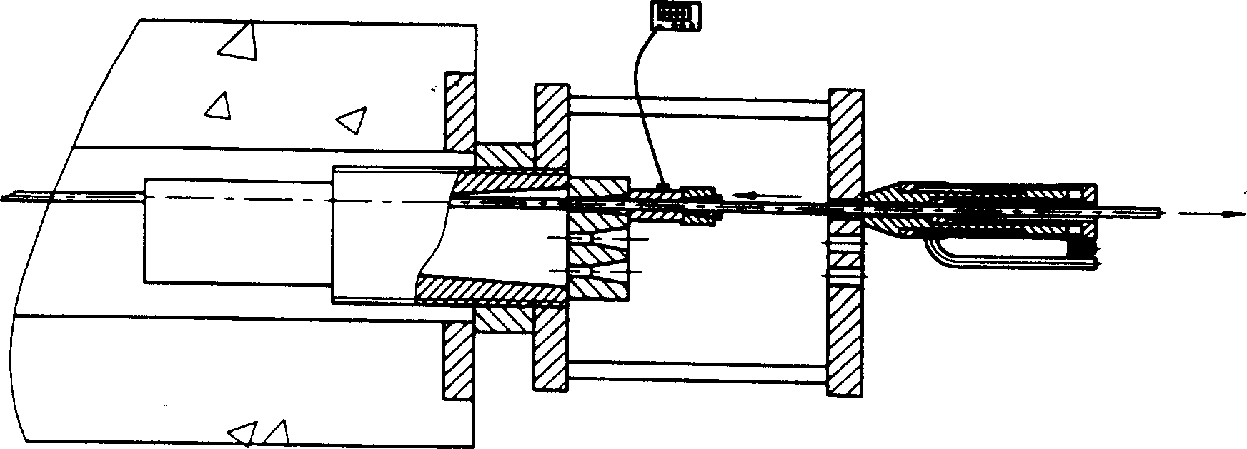
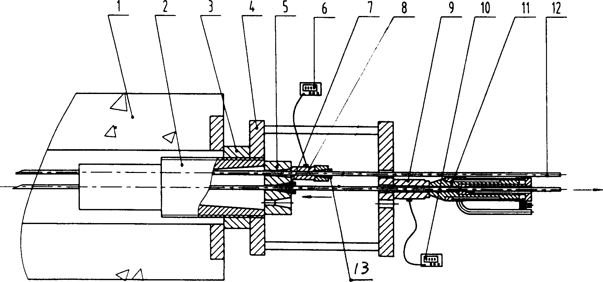
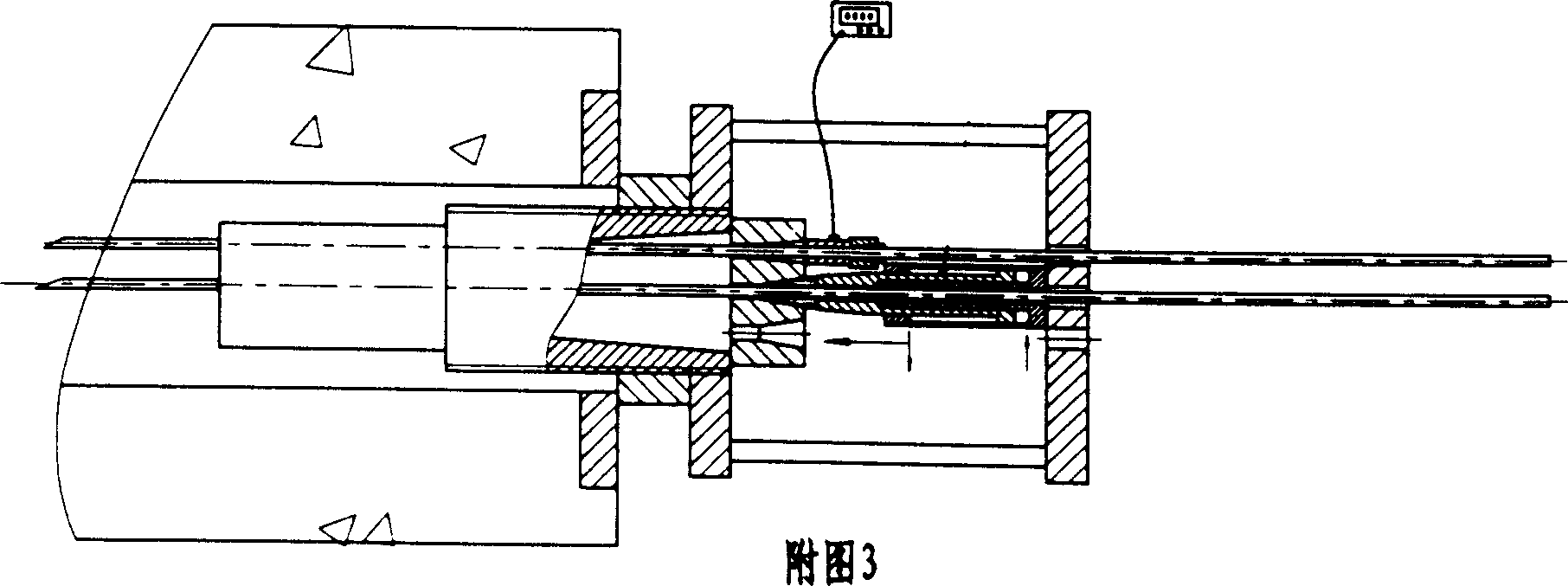
[0035] (1), install reaction force frame 4, make it be connected with supporting cylinder 2 by threaded connection; Single-hole force sensor 8 is installed on the first tensioned steel strand 12, and is connected with digital strain gauge 6, installs single Hole tool anchor assembly 13, then zero-adjust the digital strain gauge 6, use a single-hole front clip jack 13 to push against the inner side of the reaction frame 4, stretch the first steel strand 12 to the designed force value, and tighten it with a tool the tool clip in the tool anchor assembly 13;

[0036] (2), install the single-hole force sensor 9 on the second steel strand 12, and connect it with the digital strain gauge 10, and adjust zero, push the outer end surface of the reaction force frame 4 with the front clip jack 11 of the single hole Perform tensioning so that the force value displayed by the digital strain gauge 6 is consistent with the f...


PUM


Abstract

A low-stress self-anchoring method for steel guy cables includes such steps as streching the first guy cable to designed stress value, anchoring it, repeating said steps for all guy cables, restretching the first one to make the values displayed by digitial strainer consistant, reanchoring, reversely installing anchor plate and anchorage, and anchoring them. Its advantages are high reliability, high fatigue strength and low cost.

Description

technical field [0001] The invention relates to a method for self-anchoring under low stress of group anchor steel strand cables. Background technique [0002] Existing steel strand cable-stayed bridges and hanger bridges, as bridges with larger spans, have been flourishing in the construction of bridges because of their beautiful appearance and economical materials. In the application, the research mainly focuses on the material and structure of the cable. Because of its unique advantages such as convenient cable manufacturing, simple transportation, and low hoisting cost, group anchor steel strand cables have a tendency to gradually replace other cable systems. However, the group anchor cables currently used in the market all have the following problems: [0003] 1. Since the self-anchoring condition of the group anchor steel strand cable is established, the power source comes from the reaction force of the elastic extension of the steel strand,...

Claims


Application Information

Patent Timeline
Patent Type & Authority Applications(China)
IPC IPC(8): E01D11/04E01D19/14E01D19/16
Inventor 林居章刘双友尹海宜
Owner 柳州市威尔姆预应力有限公司
Why Eureka
Try Eureka