

Wire spring electric connector
An electrical connector and electrical connection technology, which is applied in the direction of connection, circuit, and contact parts, can solve the problems of unstable electrical contact, limited capacity, and malfunction, and achieve stable and reliable electrical contact, improve contact reliability, and quickly replace Effect
- Summary
- Abstract
- Description
- Claims
- Application Information
AI Technical Summary
Problems solved by technology
Method used
Image


Examples
Embodiment Construction
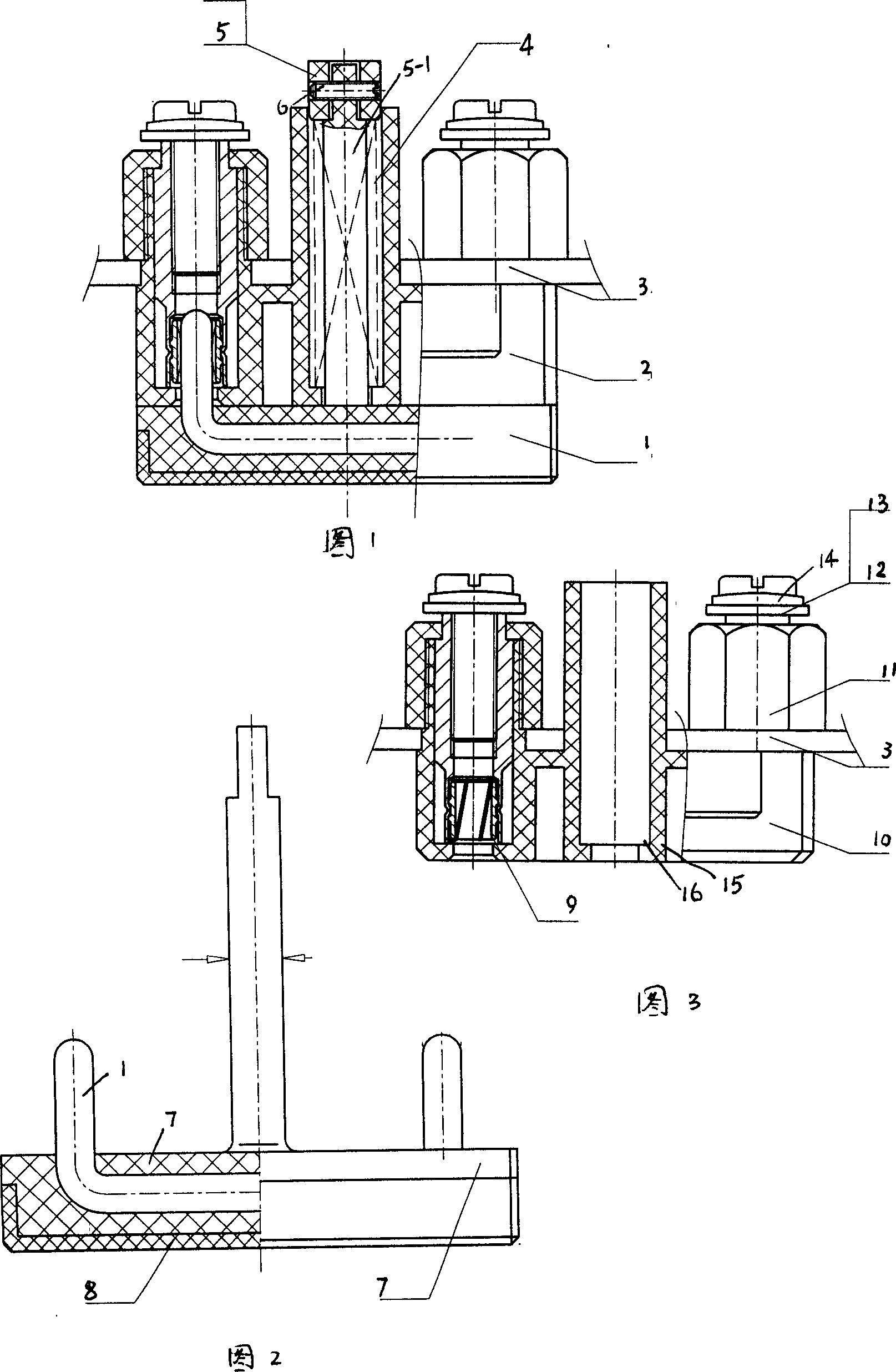
[0025] Below in conjunction with accompanying drawing and by embodiment the present invention will be further described:
[0026] This example shows the XH17W2T / DKZ electrical connector used in the relay protection cabinet.
[0027] Press and buckle the transparent plug cover plate 8 from the front of the plug insulator part 7 to form a plug assembly;
[0028] Put the two wire spring sockets 9 into the rear end of the socket insulator 10, press them tightly with a plastic nut 11, screw the terminal screw 12 with the spring washer 14 and the flat washer 13 into the threaded hole at the tail of the wire spring socket, Form the socket assembly; the wire spring jack 9 selects a kind of wire spring jack that wraps the plug by metal wire or sheet metal, and the metal wire and the metal plug are all plated with precious metals.
[0029] Insert the plug assembly and the socket assembly, set the pressure spring 4 on the central fixed rod of the plug insulator part 7, and set the plast...
PUM
 Abstract
Description
Claims
Application Information