

Trip relay
A relay and tripping technology, applied in the direction of circuits, electrical components, parts of protective switches, etc., can solve problems such as increased apparent power
- Summary
- Abstract
- Description
- Claims
- Application Information
AI Technical Summary
Problems solved by technology
Method used
Image

Examples
Embodiment Construction
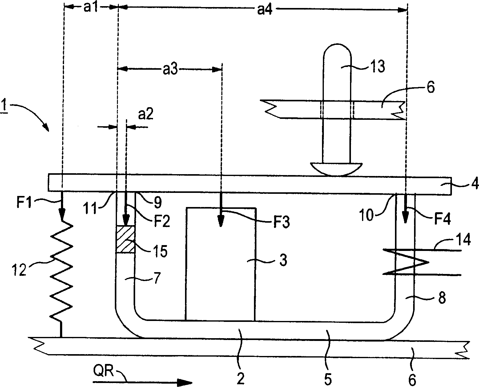
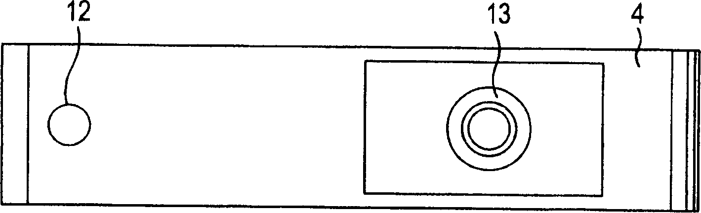
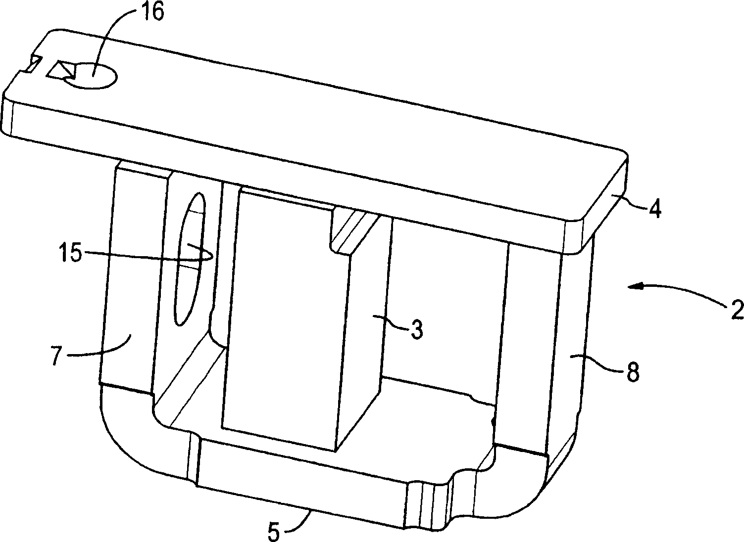
[0022] should be figure 1 , 2 , 3, 4, 5 and 6 a tripping relay 1 for a fault current protective switch shown at least partially, comprising a core or yoke 2 made of a soft magnetic material with a nickel content of 40%-85%, a permanent magnet 3 and a magnetic armature4. The yoke 2 with the bottom plate 5 leaning against the wall plate of the housing 6 includes supporting magnetic pole core legs 7 and coil magnetic pole core legs 8 respectively connected to the bottom plate 5 . The two pole core legs 7 , 8 end respectively in a pole face 9 , 10 lying on a plane, against which the magnetic armature 4 abuts. The magnetic armature 4 is a deflecting armature which can be pivoted about an edge 11 on the pole face 9 of the supporting pole core leg 7 . The edge 11 thus becomes the axis of rotation of the deflection armature 4 .
[0023] The deflection armature 4 is connected with a tension spring 12 as a tripping spring outside the yoke 2, and the tension spring exerts an active f...
PUM
 Abstract
Description
Claims
Application Information