
Conductive pressure sensitive textile

A technology of conductors and fabrics, used in textiles and papermaking, textiles, fabrics, etc., to achieve the effect of high discrimination

Inactive Publication Date: 2003-07-16
INTELLIGENT TEXTILES
View PDF1 Cites 32 Cited by
  • Summary
  • Abstract
  • Description
  • Claims
  • Application Information

AI Technical Summary

Problems solved by technology

While this fabric assembly functions well, there are unavoidable drawbacks, three or more fabric layers are necessary, additional costs are involved, the thickness of the fabric, the need to maintain alignment between the layers, the tension of the layers during use sports, wait

Method used


Image

  • Conductive pressure sensitive textile
  • Conductive pressure sensitive textile
  • Conductive pressure sensitive textile

Examples


Embodiment Construction

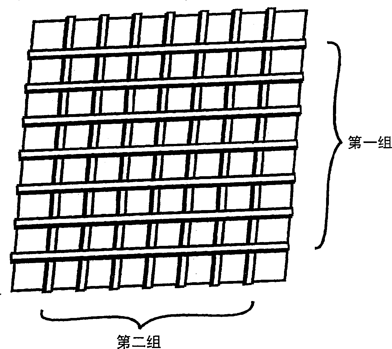
[0034] Refer to attached picture, in figure 1 In the preferred embodiment, it is desirable that the fabric includes at least two sets of elongated conductors. Typically, the conductors in each group are arranged parallel to each other, and one group of conductors is arranged perpendicular to the other to form an artificially spaced grid, such as figure 1 shown in . The elongated conductors are generally single or multi-wire conductive fibers, while the remainder of the deposit consists of insulating fibers.

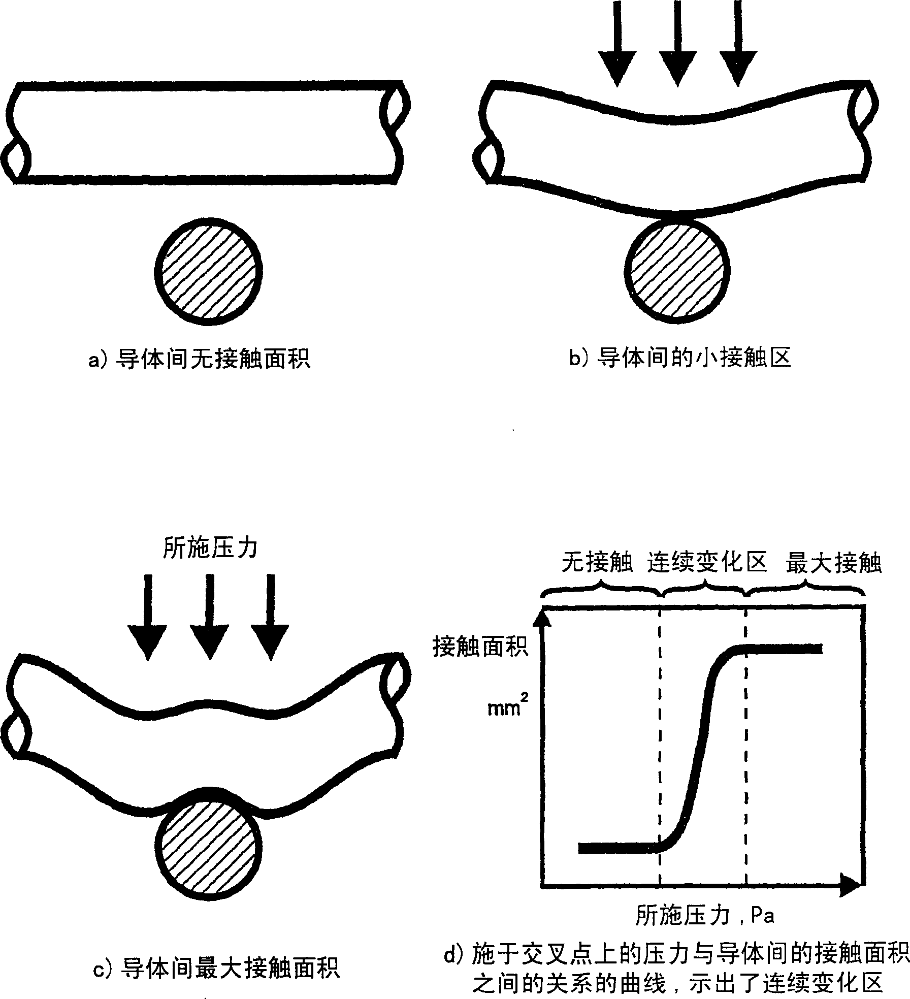
[0035] as in figure 2 As shown in the cross-sectional view of the two conductors in (a), at the point where the two conductors intersect each other, the structure of the fabric and / or conductive fibers maintains their physical separation. When pressure is applied in a direction perpendicular to the plane of the fabric, as shown in Figure (b), the conductive fibers are caused to segregate and make electrical contact. In this way, each intersection creates a momentar...


PUM


Abstract

A fabric including within its construction a first elongated electrical conductor crossed by a second elongated electrical conductor, the conductors being normally biased apart at a crossover point of said fibres with an air gap between them, whereby application of pressure in a direction substantially normal to a plane of the fabric causes the conductors to make contact. The fabric may be woven, knitted, non-woven or plaited. The fabric can be used as a pressure sensor, switch or other sensor.

Description

technical field [0001] The present invention relates to a method of fabricating one or more pressure actuated electrical switches or sensors which in preferred embodiments are used as integral elements of a single layer of fabric. Background technique [0002] Conductive fabrics are known and written about in the art, for example as described in the applicant's earlier UK patent application 2,339,495. Known electrical fabrics typically comprise two conductive layers, separated by a spacer layer, which are connected as soon as pressure is applied to the conductive layers. While this fabric assembly functions well, there are unavoidable drawbacks, three or more fabric layers are necessary, additional costs are involved, the thickness of the fabric, the need to maintain alignment between the layers, the tension of the layers during use exercise, etc. Contents of the invention [0003] The present invention seeks to provide an improved textile. [0004] According to an aspe...

Claims


Application Information

Patent Timeline
Patent Type & Authority Applications(China)
IPC IPC(8): D02G3/12D02G3/38D02G3/44D03D15/00G01L1/20G06F3/033G06F3/045H01H1/06H01H13/52H01H13/70
CPCY10T442/3293Y10T442/30Y10T442/109Y10T442/3976Y10S2/902D02G3/38Y10T442/682Y10T442/3089Y10T442/654Y10T442/3098Y10T442/649Y10T442/162Y10T442/3382Y10T442/641Y10T442/313Y10T442/339Y10T442/3114H01H2203/01G06F3/045Y10T442/3179D02G3/441Y10T428/2913Y10T442/68Y10T428/2936G01L1/20H01H2203/0085Y10T428/2915Y10T442/642Y10T442/3122
Inventor 斯坦利·施格存·斯沃洛阿莎·佩塔-汤姆森
Owner INTELLIGENT TEXTILES
Learn More