Magnetic resistance megnetic head current upright on plane structure

A planar structure, current technology, applied in the manufacture of magnetic flux sensitive magnetic heads, magnetic recording heads, magnetic field controlled resistors, etc.

Inactive Publication Date: 2003-07-23
FUJITSU LTD
View PDF0 Cites 30 Cited by
  • Summary
  • Abstract
  • Description
  • Claims
  • Application Information

AI Technical Summary

Problems solved by technology

However, in the magnetoresistive element of the CPP structure including the spin valve film, it

Method used


Image

  • Magnetic resistance megnetic head current upright on plane structure
  • Magnetic resistance megnetic head current upright on plane structure
  • Magnetic resistance megnetic head current upright on plane structure

Examples


Embodiment Construction

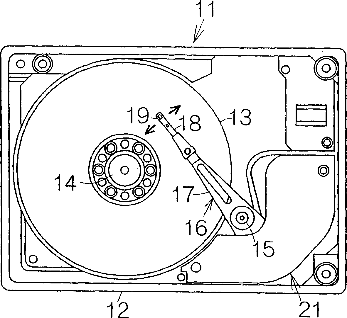
[0036] figure 1 is a schematic diagram showing the internal structure of a hard disk drive (HDD) 11 as an example of a magnetic recording medium drive or storage device. The HDD 11 includes a box-shaped main housing 12 defining a flat parallelepiped inner space. At least one recording medium or magnetic recording disk 13 is contained in an inner space within the main housing 12 . The magnetic recording disk 13 is mounted on a drive shaft of a spindle motor 14 . The spindle motor 14 is capable of driving the magnetic recording disk 13 for rotating it at a relatively high rotational speed of, for example, 7200 rpm (revolutions per minute) or 10000 rpm. A cover, not shown, is attached to the main housing 12 such that a closed interior space is defined between the main housing 12 and the cover.

[0037] A bracket 16 is also included in the inner space of the main housing 12 for swinging around the vertical support shaft 15 . The bracket 16 includes a rigid swing arm 17 extendi...


PUM


Abstract

A current-perpendicular-to-the-plane (CPP) structure magnetoresistive element (43) includes a spin valve film. A boundary (BR) is defined between electrically-conductive layers (55a, 55b) included in a non-magnetic intermediate layer (55) in the spin valve film. A magnetic metallic material (56) and an insulating material (57) exist on the boundary (BR). The insulating material (57) serves to reduce the sectional area of the path for the sensing electric current. A CPP structure magnetoresistive element (43) realizes a larger variation in electrical resistance in response to the rotation of the magnetization in the free magnetic layer (58). A sensing electric current of a smaller level is still employed to obtain a sufficient variation in the voltage. Accordingly, a CPP structure magnetoresistive element (43) embodying the present invention greatly contributes to a further improvement in the recording density and reduction in the electric consumption.

Description

technical field [0001] The present invention relates to a magnetoresistive element for reading magnetic information from a magnetic recording medium drive or a device such as a hard disk drive (HDD). Specifically, the present invention relates to a magnetoresistive element with a current perpendicular to the plane (CPP) structure, which includes a free magnetic layer, a fixed magnetic layer and a conductive non-magnetic intermediate layer. The read current is designed to include a current component perpendicular to the surface of the magnetoresistive thin film in the CPP structure magnetoresistive element. Background technique [0002] A magnetoresistive element of a CPP structure comprising a so-called multilayer large magnetoresistance (GMR) film is known. This CPP structure magnetoresistive element allows to provide a larger change in resistance as the number of magnetic layers increases. It is well known that larger changes in magnetoresistance lead to accurate reading...

Claims


Application Information

Patent Timeline
IPC IPC(8): G11B5/39H01F10/32H01L43/08
CPCH01F10/324B82Y10/00G11B5/3909B82Y25/00G11B5/3903G11B2005/3996G11B5/39
Inventor 濑山喜彥長坂惠一大岛弘敬清水丰田中厚志
Owner FUJITSU LTD
Why Eureka
Try Eureka