Eureka AIR delivers breakthrough ideas for toughest innovation challenges, trusted by R&D personnel around the world.

Semi-wave voltage test method and device for Y-waveguide modulator

A technology of waveguide modulator and half-wave voltage, which is applied in the direction of steering induction equipment, etc., can solve the problems of unstable measurement, low precision, and complicated testing process, and achieve the effect of high-precision automatic measurement

Inactive Publication Date: 2003-07-30
BEIHANG UNIV
View PDF0 Cites 8 Cited by
  • Summary
  • Abstract
  • Description
  • Claims
  • Application Information

AI Technical Summary

Problems solved by technology

Although this method has no special requirements on the modulator structure, it is also suitable for the measurement of the Y waveguide, but in this method, because it is based on the MZ interferometer, the test process is more complicated, and this interferometer is very sensitive to environmental changes. Sensitive, so this method also has the problem of measurement instability and low precision

Method used


Image

  • Semi-wave voltage test method and device for Y-waveguide modulator
  • Semi-wave voltage test method and device for Y-waveguide modulator
  • Semi-wave voltage test method and device for Y-waveguide modulator

Examples


Embodiment Construction

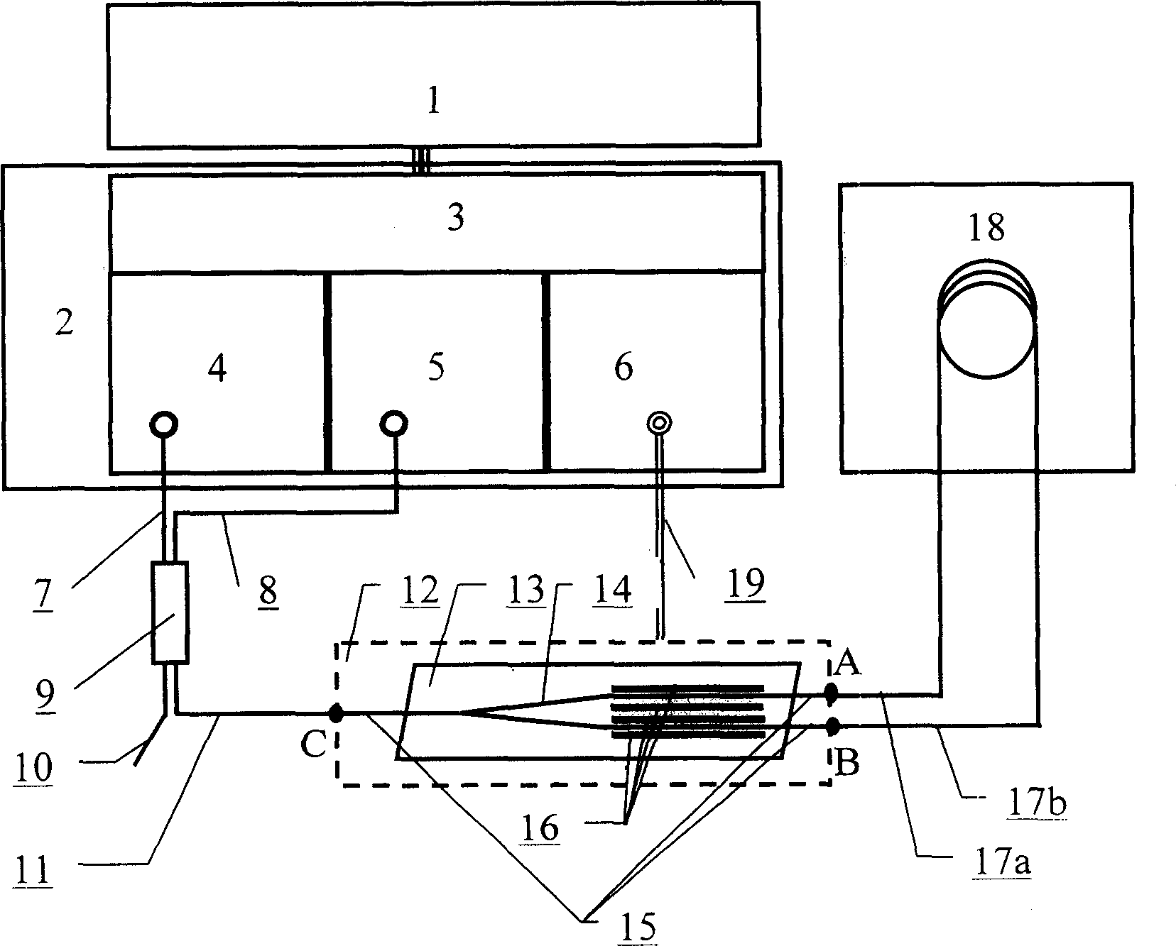
[0016] The measuring device of the present invention is composed of a micro-processing system 1 , a dedicated circuit 2 , an optical fiber coupler 9 , an optical fiber ring 18 , and a device to be measured 12 . Microprocessing system 1 undertakes the work of testing process control and result display and recording, which can be a computer, a single-chip microcomputer or other microprocessing systems with the above functions. In this example, a computer is used; special circuit 2 includes SLD and drive circuit 4 , detector and preamplifier circuit 5 and digital signal generation circuit 6, interface, control and signal acquisition circuit 3, these parts are packaged together with the power supply and installed in a special box; SLD and drive circuit 4 provide a wide spectrum for the system The stable light source, SLD is an outsourced product, and the drive circuit is also a general circuit; the detector and the preamplifier circuit 5 are realized by a detector assembly with a p...


PUM


Abstract

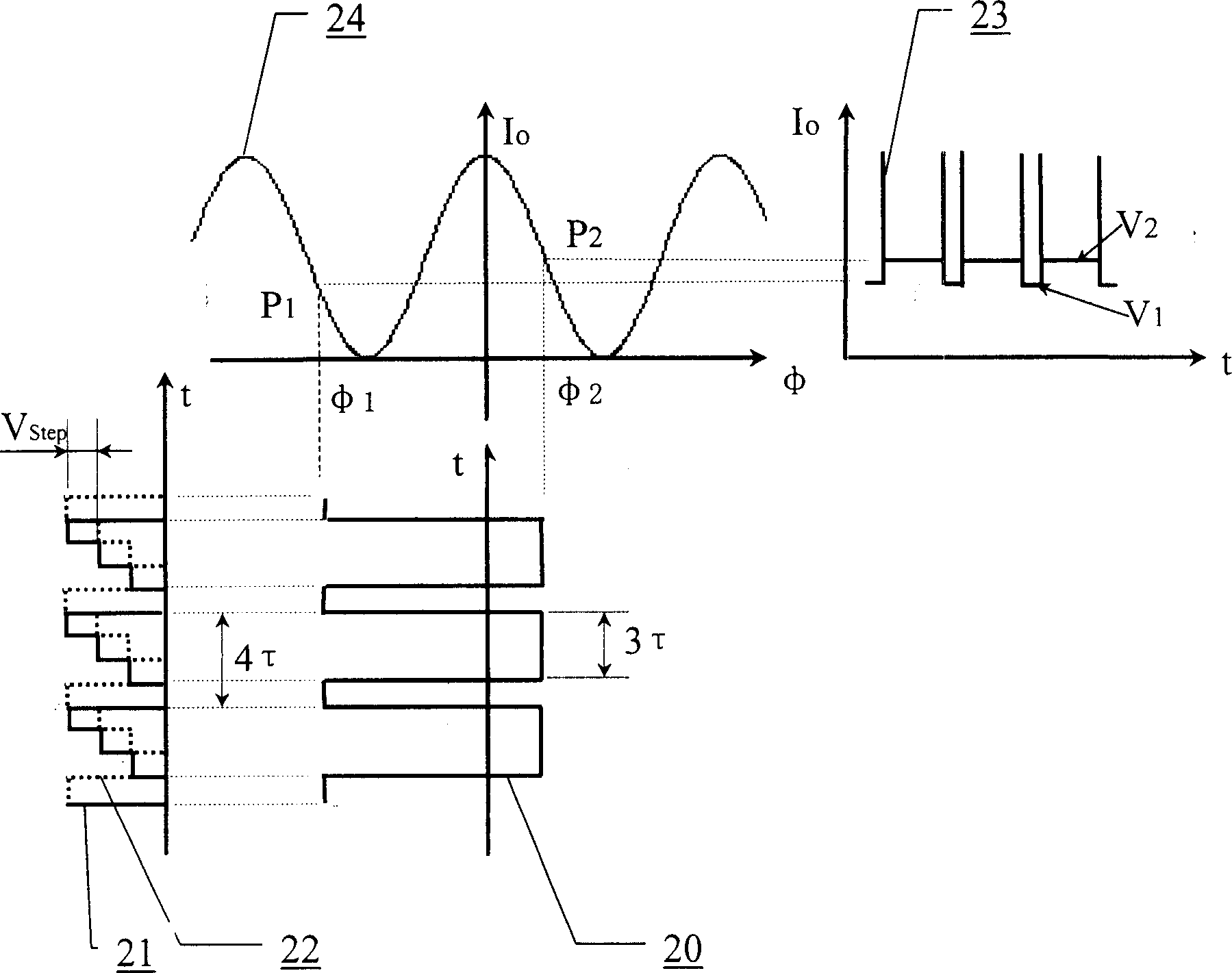
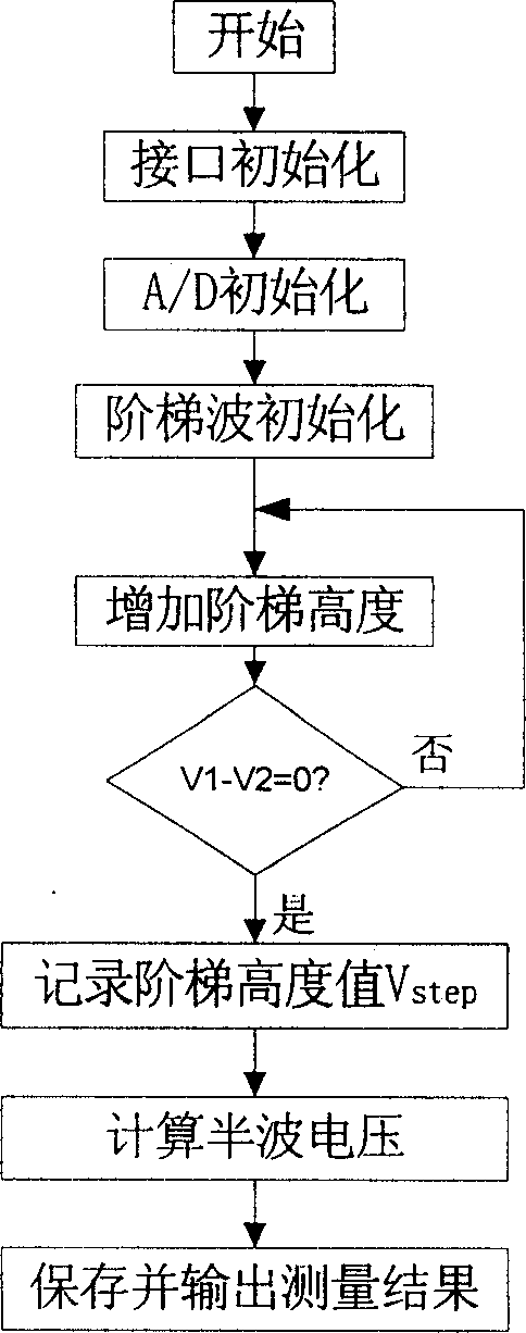
Y-waveguide to be measured is connected into Sagnac interferometer light path to form complete Sagnac interferometer. Digital stepped wave with period of 4tau, equal step height and step width of tauis applied to the modulation electrode of Y waveguide, the detector output waveform is measured via A / D technology and the difference between level V1 of the 0-tau region and the level V2 of the tau-4tau is used as the criterion. The step height is altered from high to lower, the different between V1 and V2 is calculated in computer, and when the difference is zero the step height is recorded. According to the relationship between the step height and the semi-wave voltage, the semi-wave voltage of the Y waveguide may be obtained correctly. The said method is simple and high in precision and is not affected by light power variation, light path loss and various phase errors.

Description

technical field [0001] The invention relates to a half-wave voltage testing method and device for a Y-waveguide modulator. Background technique [0002] The Y-waveguide optical modulator 12 (hereinafter referred to as the Y-waveguide) is one of the important components in the closed-loop fiber optic gyroscope (FOG), and plays the role of mode filtering (polarizer), splitting and combining light (coupler) and phase modulation ( modulator), its basic structure is as follows figure 1 As shown in the figure, the waveguides 1 and 4 are fabricated in LiNbO using a proton exchange process. 3 For the optical waveguide generated on the crystal substrate 13 , the electrodes 16 are integrated on both sides of the waveguide through a mold plating process, and the input and output of light are coupled through a polarization-maintaining fiber 15 . After adding electrical modulation wave to the electrode, through LiNbO 3 The electro-optic effect can realize the modulation of the phase o...

Claims


Application Information

Patent Timeline
Patent Type & Authority Applications(China)
IPC IPC(8): G01C19/58
Inventor 杨远洪张惟叙马静
Owner BEIHANG UNIV
Why Eureka
Eureka Blog
Learn More