Method for positioning on base and placing view-point characteristic of semiconductor piece

A substrate, viewpoint technology, used in semiconductor/solid-state device manufacturing, measurement devices, optical devices, etc.

Inactive Publication Date: 2003-08-27
TE CONNECTIVITY CORP
View PDF2 Cites 12 Cited by
  • Summary
  • Abstract
  • Description
  • Claims
  • Application Information

AI Technical Summary

Problems solved by technology

If multiple diode driver or sensor chips are mounted on a substrate connector with variations caused by the width of the

Method used


Image

  • Method for positioning on base and placing view-point characteristic of semiconductor piece
  • Method for positioning on base and placing view-point characteristic of semiconductor piece
  • Method for positioning on base and placing view-point characteristic of semiconductor piece

Examples


Embodiment Construction

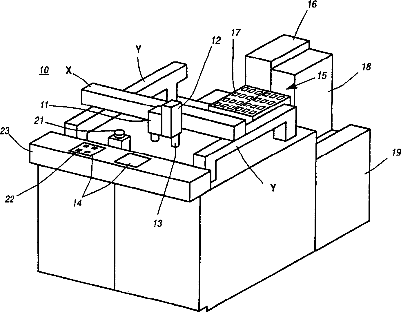
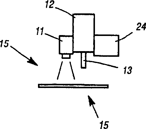
[0025] refer to figure 1 Shown is an isometric view of a typical prior art pick and place machine 10 with a downward looking camera 11 on a movable pick head 12 of the pick and place machine. The downward looking camera 11 serves several purposes. When the machine 10 is assembled, the video system and the camera 11 are used to determine the position of the pick-up nozzle 13 in the X-Y coordinate system of the machine 10, and to determine the position of the substrate 14 in the same coordinate system. The same camera is used to establish the position of the feed belt (not shown) pick station and to establish the position of the die tray 15 provided by the lift feed system 16 prior to picking the die or component 14 .

[0026] After the establishment is completed, the grid coordinates of the die tray 15 and the target position or placement position on the substrate 14 are known. What is not known is the exact position of the component 17 within the die tray 15 before picking, ...


PUM


Abstract

A pick and place machine having both a pick preview look down vision system and a horizontal vision system is employed to sense the top surface of the component before picking it up with the pick preview vision system. After pick up the horizontal vision system is employed while transporting the component to a placement position on a substrate to determine the centroid and zero rotational axis of the component and an offset correction to a desired active feature on the component. The centroid of the desired active feature on the component may then be placed on an exact predetermined point on the substrate in a minimum of time and error.

Description

technical field [0001] This invention relates to pick and place machines for mounting components on substrates and printed circuit boards and the like. More specifically, the present invention relates to a novel method for precisely aligning and placing viewpoints or features of semiconductor die with target viewpoints on a substrate, carrier, or printed circuit board. Background technique [0002] The present invention involves the use of prior art pick and place machines of which there are currently more than twenty manufacturers making and selling them in the world. Previously, components such as semiconductor chips, resistors, capacitors, and inductors were picked from feeder tape grids or waffle packs, etc., and then placed precisely on target locations on substrates or PC boards. The components to be placed cannot be picked at the optimum orientation, so some type of video system needs to be used after the components are picked and before placement to ensure proper pl...

Claims


Application Information

Patent Timeline
IPC IPC(8): G01B11/00H01L21/68H05K13/04H05K13/08
CPCH05K13/0413H01L21/681H05K13/046H05K13/0815H01L21/50
Inventor 艾伦·W·斯特拉斯曼
Owner TE CONNECTIVITY CORP
Why Eureka
Try Eureka