Automatic module configuration in a telecommunications power system and battery configuration with a click

A technology of automatic configuration and power supply system, applied in battery circuit devices, electric vehicles, secondary batteries, etc., can solve the problems of increasing the cost of acquiring and operating telecommunication power supply systems, and achieve the effect of increasing flexibility

Inactive Publication Date: 2003-08-27
VERTIV CORP
View PDF0 Cites 13 Cited by
  • Summary
  • Abstract
  • Description
  • Claims
  • Application Information

AI Technical Summary

Problems solved by technology

Requires highly trained engineers which increases the cost of acquiring and operating telecom power systems

Method used


Image

  • Automatic module configuration in a telecommunications power system and battery configuration with a click
  • Automatic module configuration in a telecommunications power system and battery configuration with a click
  • Automatic module configuration in a telecommunications power system and battery configuration with a click

Examples


Embodiment Construction

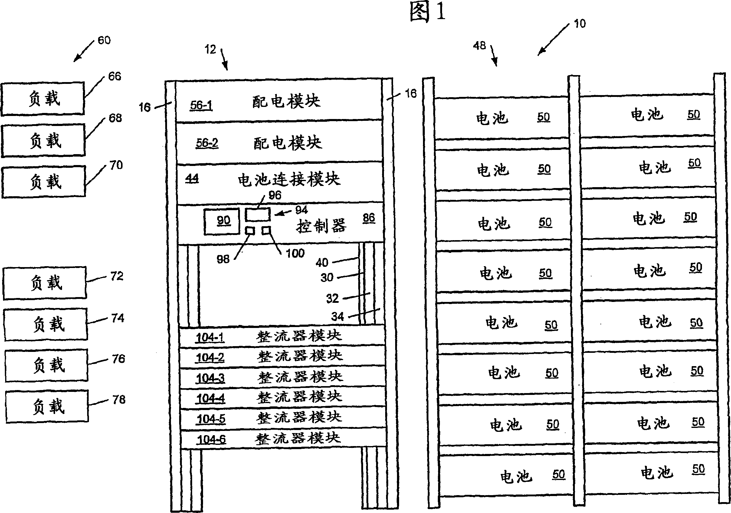
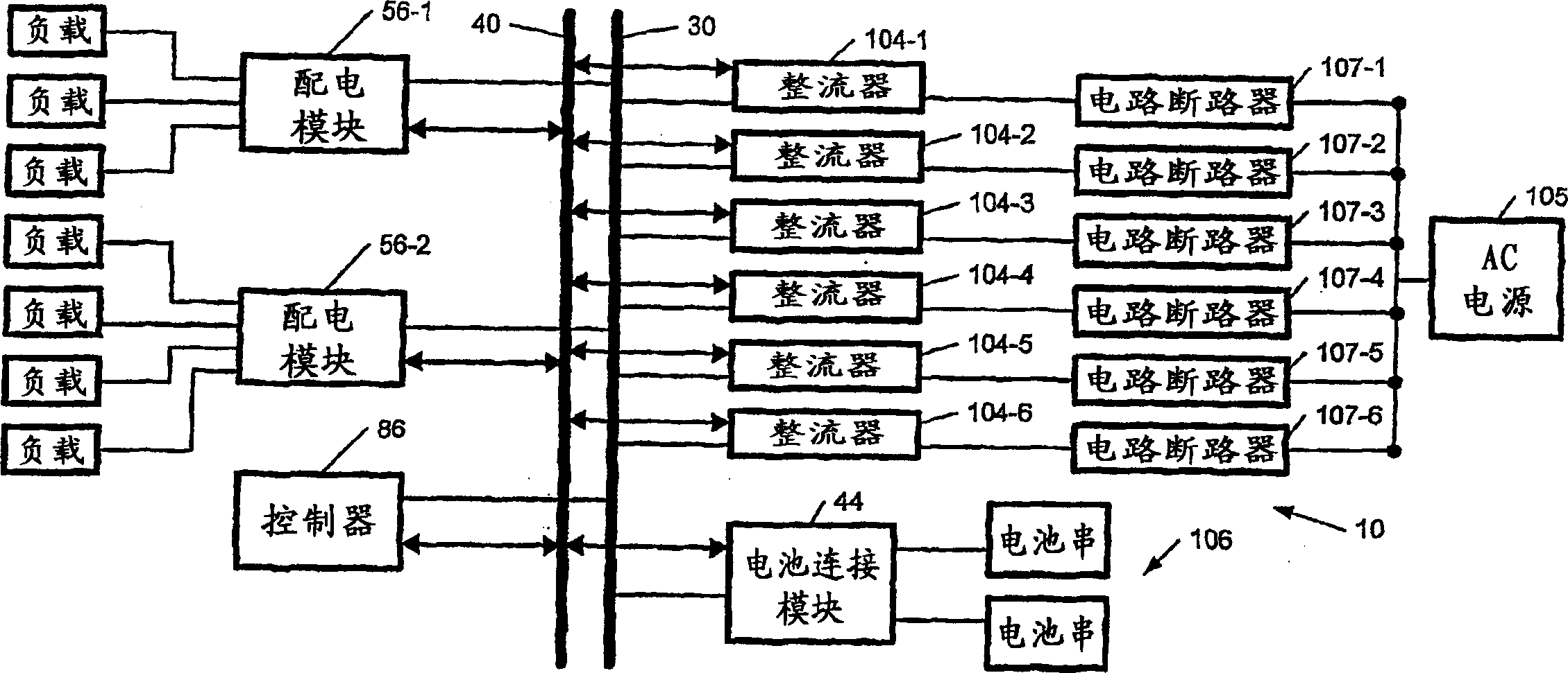
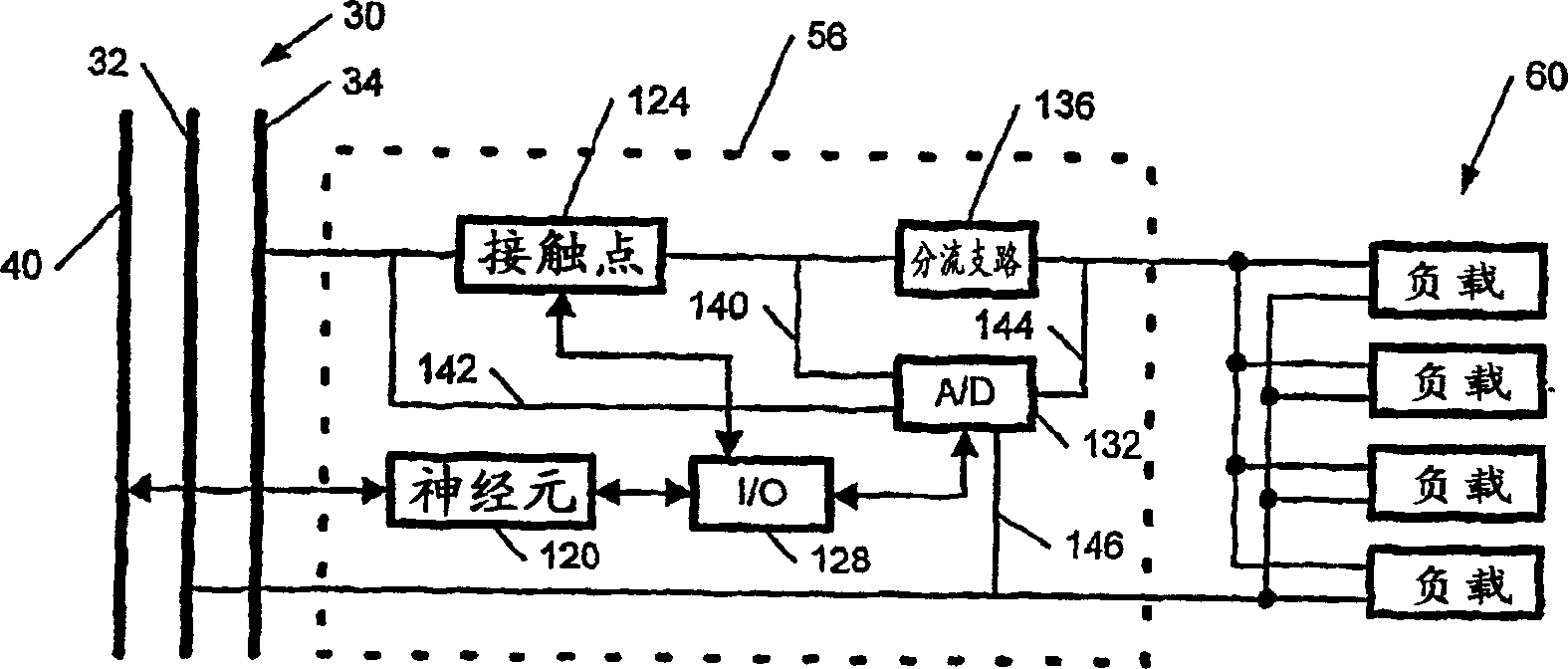
[0028] Referring now to FIG. 1 , a telecommunications power system 10 includes one or more frames 12 , wherein the frames 12 include a slide rail 16 . A direct current (DC) bus 30 includes first and second conductors 32 and 34 that extend along the slide rail 16 in a vertical direction. An insulating layer (not shown) separates the first and second wires 32 and 34 . A communication bus 40 is located adjacent to the DC bus 30 and also includes an insulating layer (not shown) to insulate the communication bus 40 from the first and second conductors 32 and 34 .

[0029] The design of the telecommunications power system 10 is modular so that the capacity of the system can be easily changed by adding or removing modules from the telecommunications power system 10 . The design of the telecommunications power system 10 has been optimized by using module connectors (not shown) to facilitate connecting and disconnecting modules from the frame 12 .

[0030] The telecommunications powe...


PUM


Abstract

An automatic configuration system for a telecommunications power system includes a power bus and a communications bus. A controller that is connected to the communication bus employs a serial communications protocol. A module transmits am identification signal to the controllert that contains an identification number of the module. The modules include rectifier modules, battery connection modules and distribution modules. Each module transmits the identification signal after the module is initially connected to the power bus and the communications bus. The controller receives the identification signal form the module. The controller stores the identification number and generates a module ID for the module that is tramsitted to the module for use by the module in further serial communications with the controller. An automated battery configuration system for a telecommunications power system includes at least one rectifier module, a controller and at least one backup battery. A database system is associated with the controller stores a plurality of records that include a plurality of backup battery parameters. A user interface that is associated with the controller receives user-provided input of at least one battery specifying parameter. The user interface communicates with the database system to retrieve a selected one of the records based on the battery specifiying parameter. The controller communicates with the database system and employs at least one of the parameters of the selected record to alter an operating setting of the telecommunications power system. The battery specifying parameters include a manufacturer designation and a model designation of the backup battery.

Description

technical field [0001] The present invention relates to telecommunications power systems. More particularly, the present invention relates to automatic module configuration in a telecommunications power system and an enhanced graphical user interface system and method for configuring a telecommunications power system to operate with different user-selected backup batteries. Background technique [0002] Telecom power systems use rectifiers that generate direct current (DC) voltage from alternating current (AC) sources. The power distribution module includes circuit breakers that connect the rectifier to the load and distribute current to the load. Typical loads in telecom power systems include telephone switches, cellular equipment, routers, and other related equipment. In the event of a loss of AC power, telecom power systems typically rely on backup batteries to provide power and avoid costly downtime due to loss of service. Telephone switches, cellular devices, and rou...

Claims


Application Information

Patent Timeline
Patent Type & Authority Applications(China)
IPC IPC(8): H01M10/42H02J1/14H02J7/34H02J13/00
CPCH01M10/4207H02J7/34H01M10/4221H02J2007/0098H02J1/14H01M10/4257H02J13/0003H02J13/00034Y02E60/10H02J13/00016H02J13/00036
Inventor 弗朗克斯·丹尼尔皮埃尔·格特克里斯蒂·德·瓦罗尼斯马奇·拉瓦格尼
Owner VERTIV CORP
Why Eureka
Try Eureka