Driving device, method and procedure of spray nozzle, liquid drop spray out device and its manufacturing method

A technology of a driving device and a driving method, which is applied to a printing device, an inking device, a device for coating liquid on a surface, etc.

Inactive Publication Date: 2003-09-17
SEIKO EPSON CORP
View PDF0 Cites 8 Cited by
  • Summary
  • Abstract
  • Description
  • Claims
  • Application Information

AI Technical Summary

Problems solved by technology

As mentioned above, the conventional nozzle driving device is designed to vibrate the piezoelectric element at high speed, and the time required for rising or falling can only be set to about 102.4 μs at the longest, so it is impossible to simply drive the nozzle for general household use. The problem that the device is used as a head drive device for a droplet discharge device that discharges a high-viscosity viscous body

Method used


Image

  • Driving device, method and procedure of spray nozzle, liquid drop spray out device and its manufacturing method
  • Driving device, method and procedure of spray nozzle, liquid drop spray out device and its manufacturing method
  • Driving device, method and procedure of spray nozzle, liquid drop spray out device and its manufacturing method

Examples


Embodiment Construction

[0049] Referring to the accompanying drawings, a device and method for driving a nozzle, a device for ejecting droplets, a program for driving a nozzle, and a device manufacturing method and device according to an embodiment of the present invention will be described in detail below. In the following description, first, an example of a device manufacturing device having a droplet ejection device, a device manufacturing device used in manufacturing a device, a device manufactured using the device manufacturing device, and a device manufacturing method will be described, and then sequentially described. The nozzle driving device, the nozzle driving method and the nozzle driver program in the output device.

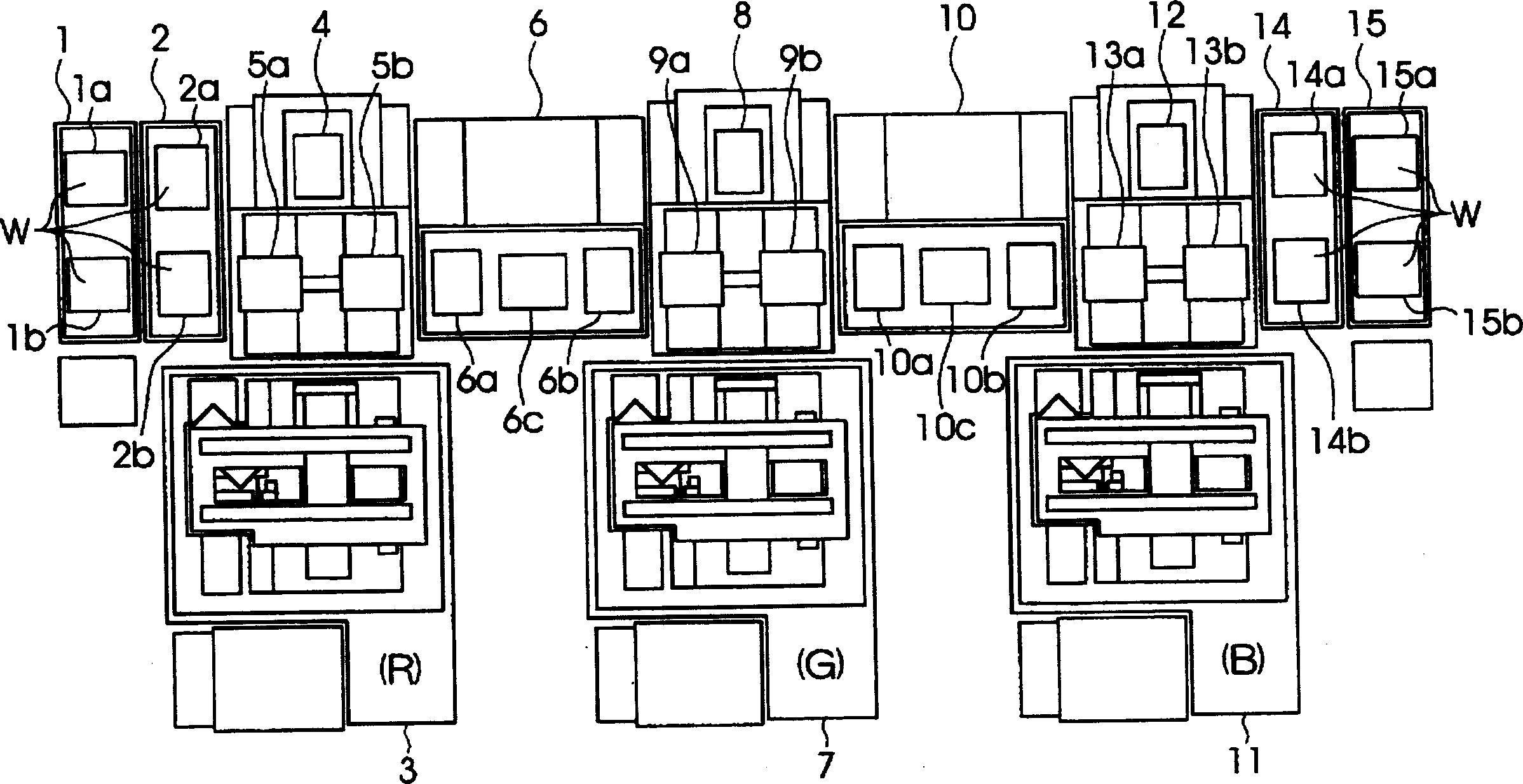
[0050] (Overall structure of device manufacturing apparatus having droplet ejection device)

[0051] figure 1 It is a plan view showing the overall structure of a device manufacturing apparatus including a droplet ejection apparatus according to an embodiment of the present...


PUM

PropertyMeasurementUnit
Viscosityaaaaaaaaaa

Abstract

To provide a head drive device and method capable of discharging a required amount of viscous material from a head having a pressure generating element such as a piezoelectric element, a droplet discharge device having the head drive device, a head driver program, and a manufacturing process One of them is a device manufacturing method having a step of ejecting the viscous body using this method. The driving signal (COM) is a signal applied to a pressure generating element such as a piezoelectric element provided on the head. Furthermore, the clock signal (CLK2) is a signal supplied to a drive signal generation circuit that generates a drive signal (COM), and the drive signal generation circuit generates the drive signal (COM) in synchronization with the clock signal (CLK2). The present invention changes the rate of change of the voltage value per unit time of the drive signal (COM) by changing the frequency of the clock signal (CLK2) in accordance with the rate of deformation of the pressure generating element per unit time.

Description

technical field [0001] The present invention relates to a nozzle driving device and method, a droplet ejection device, a nozzle driver, and a device manufacturing method and device, in particular to a nozzle driving device and method for driving a nozzle that ejects a viscous body such as liquid resin with high viscosity , a droplet ejection device having the head drive device, a head driver program, and a liquid crystal display device, an organic EL (Electro luminescence) display, and a color filter that include, as one of the steps, the step of ejecting a viscous body by the above-mentioned method Device fabrication methods and devices for substrates, microlens arrays, optical elements with coatings, and other devices. Background technique [0002] In recent years, various electronic devices such as computers and portable information devices have been rapidly developed. With the development of these electronic devices, electronic devices equipped with liquid crystal displa...

Claims


Application Information

Patent Timeline
IPC IPC(8): B41J2/01B05C5/00B05C11/10B41J2/045B41J2/055G02B5/20G02F1/1335
CPCB41J2/04541B41J2/04553B41J2/04563B41J2/04573B41J2/04581B41J2/04588B41J2002/0052B41J2202/09B41J29/00
Inventor 臼田秀范
Owner SEIKO EPSON CORP
Why Eureka
Try Eureka