

Supersonic speed direct heating heater
A direct heating and heater technology, applied in fluid heaters, heating methods, lighting and heating equipment, etc., can solve problems such as loud noise
- Summary
- Abstract
- Description
- Claims
- Application Information
AI Technical Summary
Problems solved by technology
Method used
Image

Examples
Embodiment 1
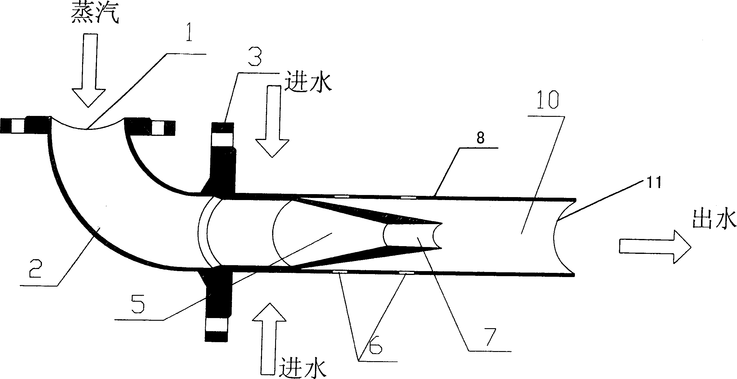
[0019] see figure 2 Shown is the structural sectional view of the present invention. A supersonic direct heating heater of the present invention comprises:
[0020] A main housing 8 is in the shape of a circular tube, one end of the main housing 8 is fixedly connected to the integral fixed flange 3, and there are evenly distributed holes on the wall surface of the main housing 8 near the end 1 / 4 of the integral fixed flange 3. The water inlet 6, the quantity of the water inlet 6 is 2-6, the best is 4; the other end of the main housing 8 is a water outlet 11; wherein between the critical nozzle 7 and the water outlet 11 is a cylinder Shaped high-pressure mixing chamber 10;
[0021] A nozzle 5 is funnel-shaped, and the nozzle 5 is accommodated in the main housing 8, and the large-diameter end of the nozzle 5 is fixedly connected to the integral fixing flange 3; a critical nozzle 7 is long trumpet-shaped, and the critical The nozzle 7 is fixedly connected to the small diamete...
Embodiment 2
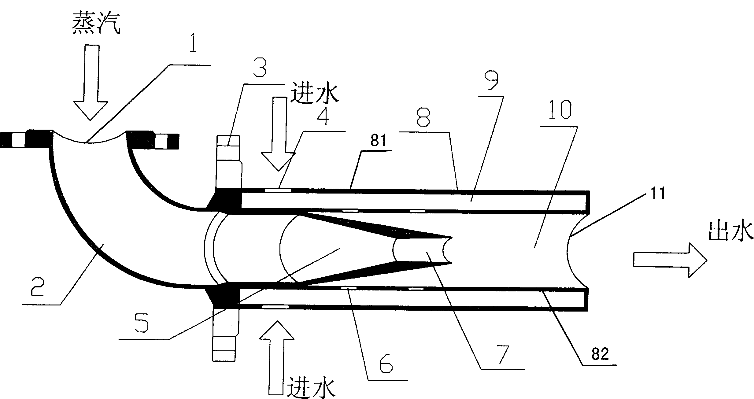
[0026] see image 3 As shown (wherein the same components in the accompanying drawings use the same reference numerals), the present embodiment is basically the same as the first embodiment, the difference is that its main housing 8 is a double-layer structure, including an outer wall 81 and an inner wall 82 A sound-absorbing and vibration-isolation cavity 9 is formed between the outer wall 81 and the inner wall 82, and water inlet holes 4 are evenly distributed on the end of the outer wall 81 close to the integral fixed flange 3, and the number of the water inlet holes 4 is 2-6 , preferably 4.
[0027] When the water enters the high-pressure mixing chamber 10 through the water inlet 4 on the outer wall of the main shell 8 of the heater through the sound-absorbing and vibration-isolating cavity 9 and then from the water inlet 6 on the inner wall of the main shell 8, due to the noise Due to the effect of the vibration isolation cavity 9, the working noise and movement can be f...
Embodiment 3
[0029] see Figure 4 As shown (wherein the same parts in the drawings use the same reference numerals), the present embodiment is substantially the same as the second embodiment, the difference being that one end of the main housing 8 away from the integral fixing flange 3 is affixed with a Conical conical decompression damping body 13, the conical end of the conical decompression damping body 13 extends into the main housing 8 and the tail end is affixed to the main housing 8; the main housing 8 is far away from the integral fixed flange 3 There are water outlets 12 on the wall at one end, the number of the water outlets 12 is 2-6, the best is 4.
[0030] When the water enters the high-pressure mixing chamber 10 through the water inlet 4 on the outer wall of the main shell 8 of the heater through the sound-absorbing and vibration-isolating cavity 9 and then from the water inlet 6 on the inner wall of the main shell 8, due to the noise With the function of the vibration isola...
PUM
 Abstract
Description
Claims
Application Information