Method for automatic controlling voltage of electrical power system

An automatic voltage and power system technology, applied in the direction of AC network voltage adjustment, reactive power compensation, etc., can solve the problems of low pass rate of bus voltage, poor control function, and no consideration of the change trend of control quantity, etc.

Inactive Publication Date: 2003-10-01
STATE GRID CHONGQING ELECTRIC POWER
View PDF0 Cites 7 Cited by
  • Summary
  • Abstract
  • Description
  • Claims
  • Application Information

AI Technical Summary

Problems solved by technology

For the first and second control methods, in the existing control methods, because the control variables (bus voltage U, reactive power Q) are too thick, the bus voltage and reactive power are only controlled by upper and lower limits It is divided into three areas: qualified, exceeding the upper limit, and exceed...

Method used


Image

  • Method for automatic controlling voltage of electrical power system
  • Method for automatic controlling voltage of electrical power system

Examples


Embodiment Construction

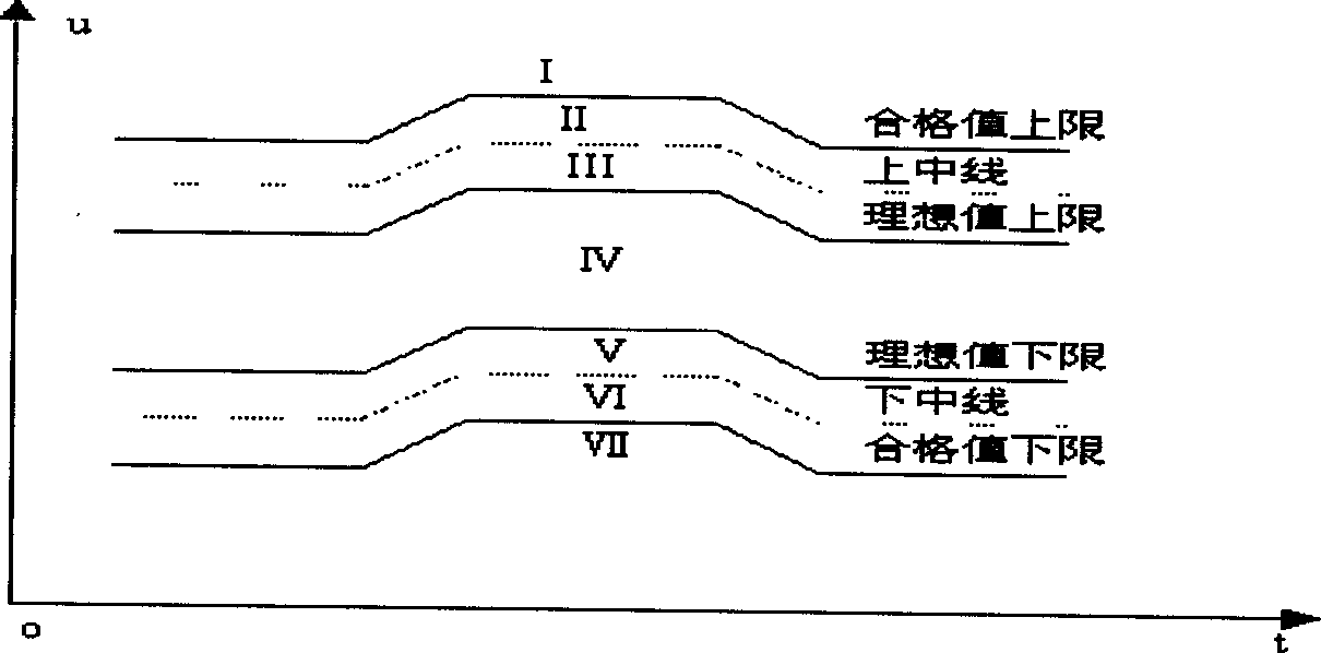
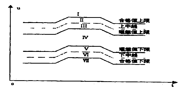
[0025] The attached figure shows the busbar voltage curve after the actual application of the 500kV Changshou substation of Chongqing Electric Power Company.

[0026] The change judgment of the change trend of the monitored voltage (values ​​include the priority guaranteed voltage and the monitored voltage) is to compare the sampling values ​​at intervals of a second to judge the change trend of the voltage. which is

[0027] When U ta -U t0 When ≥m kV, it is defined as a voltage rise ("rise");

[0028] When U t0 -U ta ≥m kV, defined as a voltage drop ("drop");

[0029] When|U ta -U t0 When |

[0030] The values ​​of a and m are determined by the user and can be modified according to the value notification. In the embodiment: the busbar voltage adopts the interval a=1 minute; m=0.1 kV; the highest operating voltage U of the reactive equipment max = 40 kV; acceleration cut interval b = 60 seconds; unlocking differentia...


PUM


Abstract

An automatic voltage control method for power supply is to divide bus voltage U into seven control areas, and the operation mode of reactive equipment is controlled automatically according to three voltage changing trends of rising, remaining unchanged, and dropping measured actually at the bus in each control area, i.e realizing the accurate control of bus voltage by switching on or switching off the capacitor set and by regulating the on-load voltage regulation switch for obtaining relatively ideal reactive tide and better on-specification rate of voltage.

Description

technical field [0001] The present invention relates to an automatic control method for voltage and reactive power in a power system, that is, a method for automatic voltage control by finely partitioning control quantities (bus voltage U, main transformer input reactive power Q) and combining the changing trend of control quantities . technical background [0002] At present, the comprehensive automatic control devices for voltage and reactive power operating in the power system all use the principle of nine-zone diagram to control reactive power and bus voltage. [0003] According to whether there is a capacitor (reactor) group and the type of transformer tap switch, it can be divided into three control methods: 1. With capacitor (reactor) group and the transformer is an on-load tap switch: comprehensive control of reactive power and voltage , the goal is to control the bus voltage and reactive power between the specified upper and lower limits; 2. There is a capacitor (r...

Claims


Application Information

Patent Timeline
IPC IPC(8): H02J3/16
CPCY02E40/30
Inventor 邹景行许道林刘绍亭龙小平
Owner STATE GRID CHONGQING ELECTRIC POWER
Why Eureka
Try Eureka