
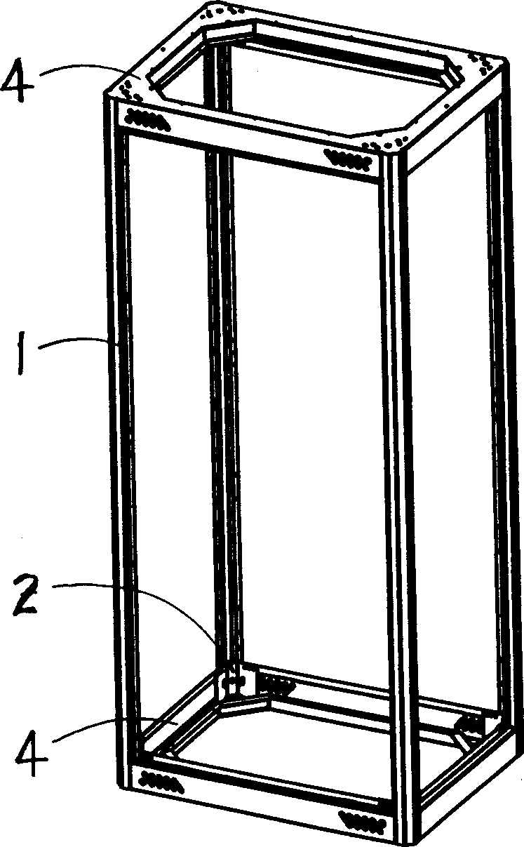
Assembling type rack frame structure

A prefabricated and cabinet technology, applied to substation/switchgear frames, detachable cabinets, cabinets, etc., can solve problems such as waste, unreported, waste of capacity, etc.

Inactive Publication Date: 2003-10-22
上海惠亚电子有限公司
View PDF1 Cites 17 Cited by
  • Summary
  • Abstract
  • Description
  • Claims
  • Application Information

AI Technical Summary

Problems solved by technology

[0002] It is very common to use rectangular cabinets such as electrical cabinets, switch cabinets, packaging cabinets, etc. in the industrial and agricultural production process. The structure generally adopts welding and riveting methods. Once formed, it is permanently fixed. This traditional cabinet can have sufficient strength. , but the processing is time-consuming and labor-intensive. In order to overcome the deformation problems caused by welding and riveting, some of them need to be heat-treated to overcome the internal stress, so as to ensure the smoothness and beauty of the cabinet and the installation of plug-in components.
Because the cabinet is integral, once the cabinet is damaged, even if it is a small damage, it must be scrapped as a whole, causing a lot of waste
The overall structure of the cabinet makes the transportation of empty cabinets cause a waste of transport capacity, which is also a defect that cannot be ignored
In recent years, people have made a lot of efforts and attempts in cabinet processing, and put forward many improvement measures to overcome the defects of traditional technology. Metal frame structure with corner fasteners "US Patent [Patent No.: us6299268B1], in which the engagement between the beams and columns of the fabricated frame is accomplished through specially designed corner connectors, which are one piece Metal castings with complex shape, complex processing technology, trapezoidal cross-section with front opening and rear closing including acute angle range of 20° to 40° are used for all metal sheet metal materials, simple structure, convenient processing and installation, and sufficient strength and rigidity. Assembled cabinets have not been reported

Method used


Image

  • Assembling type rack frame structure
  • Assembling type rack frame structure
  • Assembling type rack frame structure

Examples


Embodiment Construction

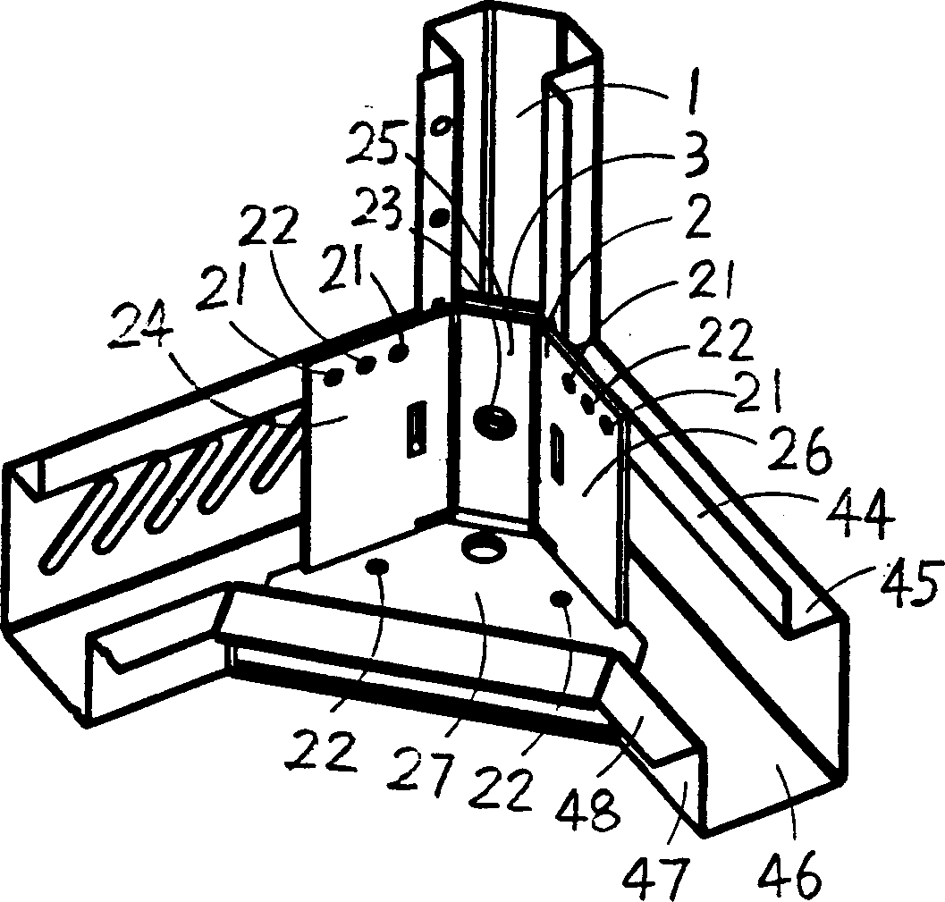
[0044] A frame with a height of 2 meters, a width of 0.6 meters and a depth of 0.6 meters is implemented through the following steps: (1) corner column 1: adopt 1.5 mm thick galvanized iron plate through stamping and bending. Forming a long 2-meter cross-section is a symmetrical hexagonal rhombus (such as figure 2 shown);

[0045] (2) Corner connection block 2: 3mm thick cold-rolled steel plate is used for stamping, bending, spot welding, and processed into a right-angled sheet metal component (such as figure 2 shown);

[0046] (3) Corner tight block 3: 3 mm thick cold-rolled steel plate is used for stamping, bending, and processed into three-fold tile-shaped sheet metal components (such as Figure 7 shown);

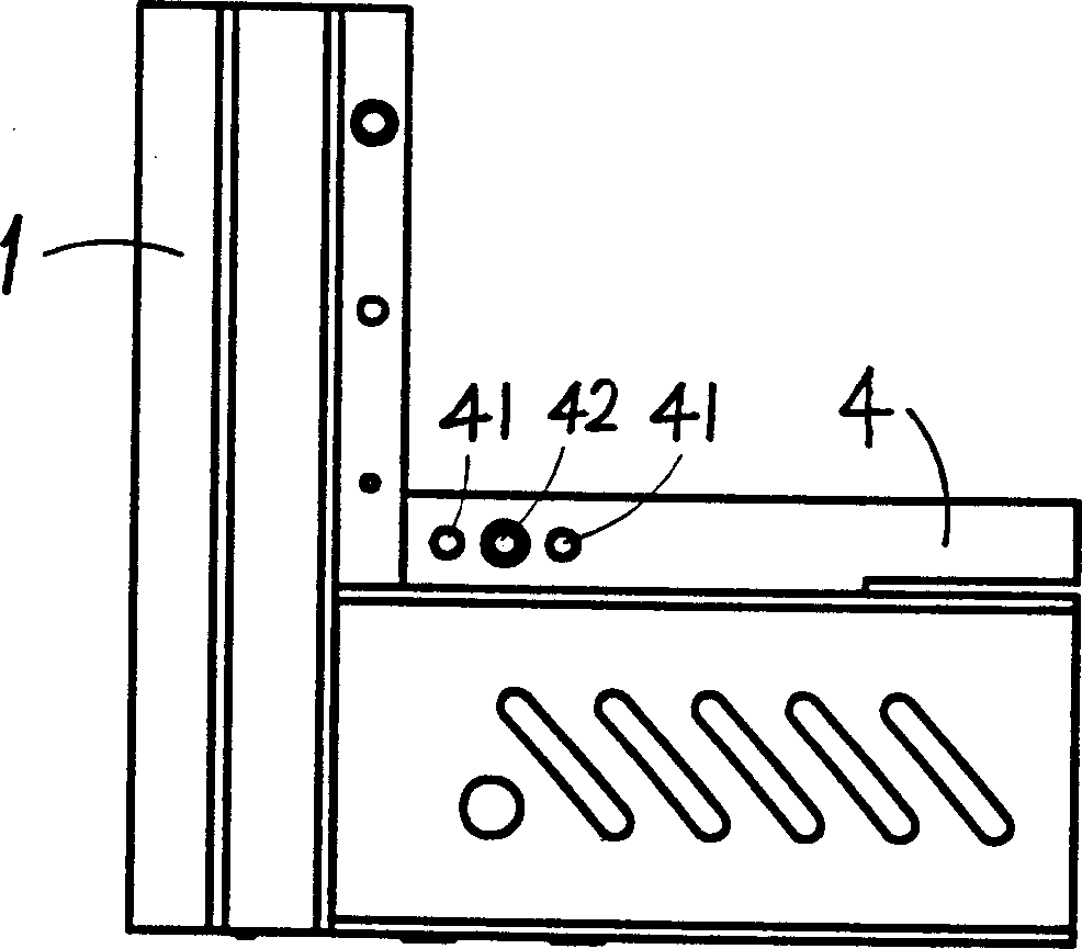
[0047] (4) Base 4: use 1.5 mm thick galvanized metal member after punching, bending, and processing into a rectangular frame sheet metal member of 0.6 m x 0.6 m, whose cross-sectional shape is like a rectangular tube with an opening at one corner (such as figure 2 sh...


PUM


Abstract

The present invention relates to a machine cabinet frame structure, in particular, it relates to a frame assembled by using upper and lower base seats and four corner upright columns, and the structure of every frame corner is made up by adopting corner upright column, corner connecting blocks, corner inner fastening blocks and base seat and directing, positioning, mounting and fixing the above-mentioned four metal sheet members. The above-mentioned metal members having good university and interchangibility, so that said invention can assemble various rectangular machine cabinets with different sizes.

Description

Technical field: [0001] The invention relates to a frame structure of a cabinet, in particular to a frame structure of an assembled cabinet. Background technique: [0002] It is very common to use rectangular cabinets such as electrical cabinets, switch cabinets, packaging cabinets, etc. in the industrial and agricultural production process. The structure generally adopts welding and riveting methods. Once formed, it is permanently fixed. This traditional cabinet can have sufficient strength. , but the processing is time-consuming and labor-intensive. In order to overcome the deformation problems caused by welding and riveting, some of them need to be heat-treated to overcome the internal stress, so as to ensure the smoothness and beauty of the cabinet and the installation of plug-in components. Because the cabinet is integral, once the cabinet is damaged, even if it is a small damage, it will be scrapped as a whole, causing a lot of waste. The overall structure of the cabi...

Claims


Application Information

Patent Timeline
IPC IPC(8): A47B47/00F16S3/04H02B1/01
CPCH02B1/014
Inventor 胡建龙
Owner 上海惠亚电子有限公司
Learn More