Melt spinning apparatus

A technology of melt spinning and spinning components, which is applied in the direction of melt spinning, textile and paper making, spinneret assembly, etc., and can solve the problems of replacing the spinning component body, etc.

Inactive Publication Date: 2003-11-12
TORAY ENG CO LTD
View PDF2 Cites 8 Cited by
  • Summary
  • Abstract
  • Description
  • Claims
  • Application Information

AI Technical Summary

Problems solved by technology

[0006] However, the spinning assembly needs to be cleaned repeatedly and frequently. In the above-mentioned device, for example, the male thread is made into a style with a smaller outer diameter, but in the process of processing, the male thread should not be damaged. It has to be

Method used


Image

  • Melt spinning apparatus
  • Melt spinning apparatus
  • Melt spinning apparatus

Examples


Embodiment Construction

[0024] Embodiment of the invention

[0025] Hereinafter, the present invention will be described in detail with reference to the drawings, but the present invention is of course not limited to the embodiments described below.

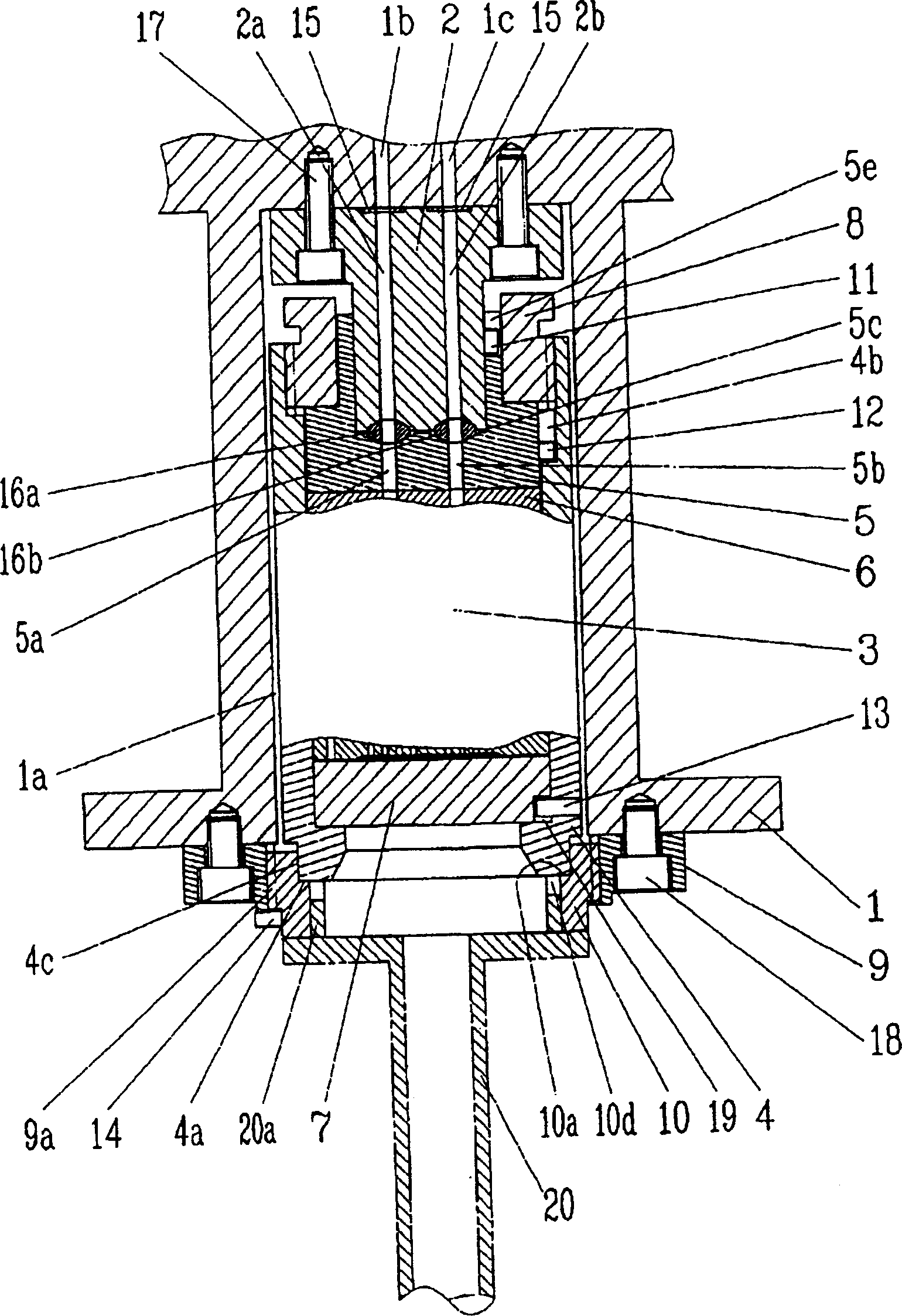
[0026] figure 1 It is a schematic cross-sectional view showing one embodiment of the structure of a melt spinning apparatus provided with a plurality of polymer flow paths according to the present invention. The melt spinning apparatus is composed of the following components, namely: a heating box provided with a spinning package housing portion 1a 1; the polymer introduction flow path 2a, 2b communicated with the polymer flow path 1b, 1c of the heating box body 1 is set penetratingly, and is installed in the heating box body 1 with the gasket 15 for sealing, with the bolt 17 Spinning assembly connecting body 2 on the upper wall of spinning assembly housing part 1a; spinning assembly 3 engaged with above-mentioned spinning assembly connecting body 2 by...


PUM


Abstract

The invention provides a melt-spinning device which can prevent the damage to a pack body, can press up a spinning pack to mount the spinning pack in a spinning pack receiver without rotating the spinning pack, can surely coincide polymer passages each other even in a case of a plurality of the polymer passages, and can always arrange the nozzle of a spinneret at a fiber-arranging position optimizing the cooling of the fiber with a cooling gas flow. This melt-spinning device is assembled by preliminarily heating the spinning pack into which a polymer guide member 5 is incorporated, fitting the lower step portion 4c of the spinning pack body 4 into the holding face 10a of a holder 10 mounted on a spinning pack-mounting tool 20, placing inlet packings 16a, 16b on the polymer guide member 5, and pressing up the spinning pack-mounting tool 20 to insert the spinning pack 3 into the spinning pack receiver 1a, and threadedly engaging the holder 10 with a screw member 9 to hold the spinning pack 3 at a prescribed position.

Description

technical field [0001] The present invention relates to a melt-spinning device (including spinning), which is a melt-spinning device capable of loading and unloading a spinning assembly from the bottom of a heating box. Background technique [0002] In general, a melt spinning device for spinning synthetic fiber filaments is composed of the following components, that is, after receiving the molten raw material (hereinafter, referred to as polymer) fed by pressure from the outside, metering and distributing it to the spinning pack Components; after the above-mentioned polymers are accommodated, they are heated and kept warm; they are installed on the space for installing the spinning pack (hereinafter referred to as the spinning pack housing part) on the lower side of the heating box. spinning components, etc. And, in the case of installing the above-mentioned spinning pack accommodating part from below, the spinning pack described in Japanese Patent Application Publication ...

Claims


Application Information

Patent Timeline
IPC IPC(8): D01D4/08D01D5/08
Inventor 森木克一
Owner TORAY ENG CO LTD
Why Eureka
Try Eureka