Camera calibrating method and its implementing apparatus

A camera calibration and camera technology, which is applied to measurement devices, camera devices, optical devices, etc., can solve problems such as moving out of the field of view, unclear imaging, and inability to achieve automatic calibration, achieving stable and reliable application and improving speed. and the effect of the degree of automation

Inactive Publication Date: 2003-11-12
TIANJIN UNIV
View PDF0 Cites 37 Cited by
  • Summary
  • Abstract
  • Description
  • Claims
  • Application Information

AI Technical Summary

Problems solved by technology

There is a method that can realize automatic calibration to establish a coordinate system with the center of the circular hole on a certain edge of the target as the origin. When the angle is large, the origin of the spatial coordinates set at the edge of the target will be unclear or move out of the field of view
Therefore, this method cannot fully automatically obtain the origin of the object space coordinates, and cannot achieve real automatic calibration

Method used


Image

  • Camera calibrating method and its implementing apparatus
  • Camera calibrating method and its implementing apparatus
  • Camera calibrating method and its implementing apparatus

Examples


Embodiment Construction

[0014] The present invention will be further described below in conjunction with the accompanying drawings and examples.

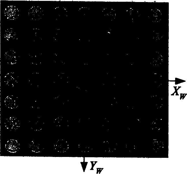
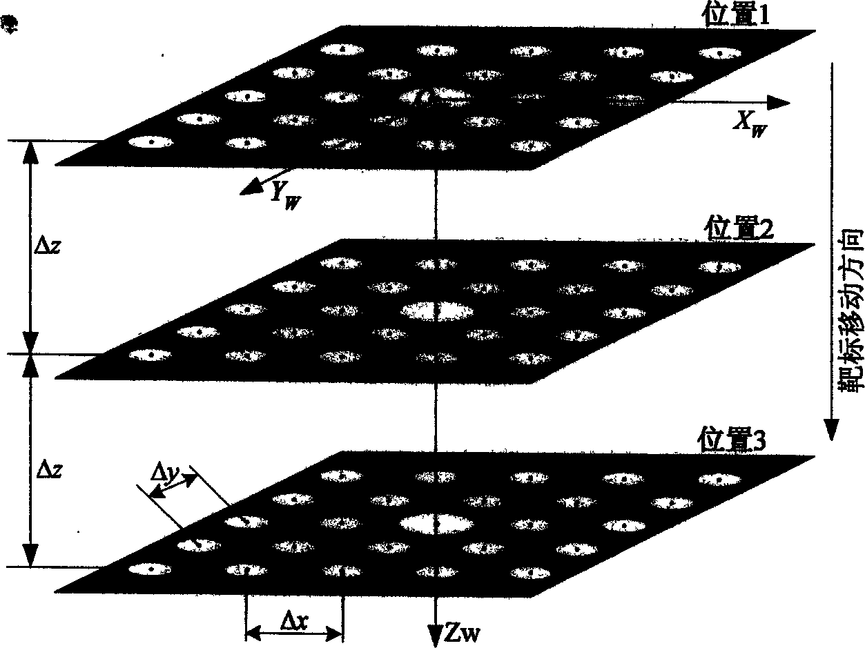
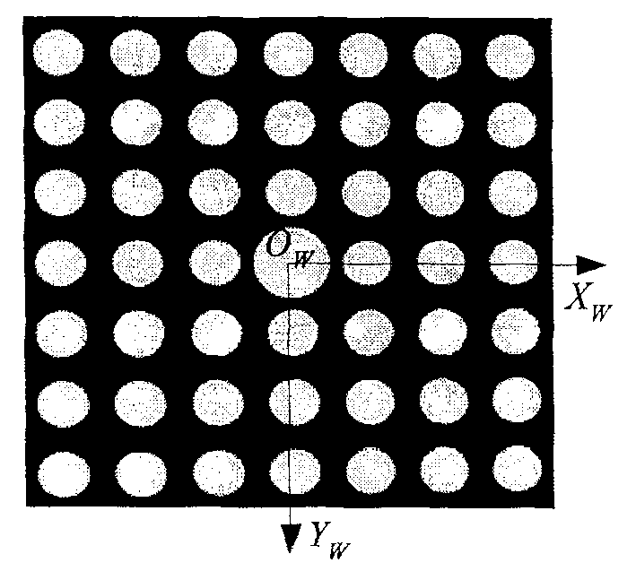
[0015] figure 1 It is a circular target of the present invention, and the circular target is a series of light-transmitting circular hole arrays M×N photoetched on an opaque flat glass, the rows and columns are strictly vertical, and the center-to-center distances of the circular holes are equal and known (Δx, Δy ). The difference from the traditional target is that the radius of the marked hole in the center of the circular target is larger than the rest of the holes. During the calibration process, the center of the marked circular hole at the first position of the circular target is taken as the origin O w , the line where the horizontal center of the circle is located is X w Axis, the line where the longitudinal center of the circle is located is Y w Axis, with the moving direction of the circular target as Z w Axis, establish a space coordinate s...


PUM


Abstract

In the invention, the mark aperture radius of the circular target drone is 120%-150% of the rest aperture. In the process, according to the filtering noise of images, threshold segmentation, contour tracing, ellipse recognition, ellipse fitting and center extraction are utilized. Based on the spetial position between the center of the marked aperture and the center of the nearest aperture as well as the distances between the center of the marked aperture and the centers of other apertures and the distance of moving the circular target drone along a certain direction, the position of the camera is determined by using the unique point space orientation method. The invention is suitable to calibration of camera in order to obtain the coincidence relation between the point in 3D space and the pixel in computer image.

Description

technical field [0001] The invention relates to the field of computer vision detection, in particular to the occasion of calibrating the camera in order to obtain the corresponding relationship between the spatial point and the pixel point of the computer image. Background technique [0002] In the process of computer vision detection, in order to obtain the corresponding relationship between spatial points and computer image pixels, camera calibration is essential. Camera calibration is to obtain the internal geometric and optical characteristics of the camera, that is, internal parameters, and the positional relationship of the camera coordinate system relative to the space coordinate system, that is, external parameters. [0003] At present, Tsai's RAC calibration method is the most commonly used. This method first solves most of the parameters of the camera model by radial collimation constraints, and then uses an iterative method to find ot...

Claims


Application Information

Patent Timeline
Patent Type & Authority Applications(China)
IPC IPC(8): G01B11/24G01B21/00G01C11/02
Inventor 孙长库王志雄张效栋
Owner TIANJIN UNIV
Why Eureka
Try Eureka