Hydromechanical speed-change device and vehicle having speed change device mounted thereon

A speed change device, mechanical technology, applied in motor vehicles, mechanical equipment, power units, etc., can solve the problems of working oil deterioration, difficult working oil characteristics, mixed with oil residues, etc., and achieves easy cooling, improved maintenance, and improved maintenance. Effects of degrees of freedom

Inactive Publication Date: 2003-11-19
SAUER DANFOSS DAIKIN
View PDF1 Cites 17 Cited by
  • Summary
  • Abstract
  • Description
  • Claims
  • Application Information

AI Technical Summary

Problems solved by technology

However, in general, the operating oil of a hydrostatic transmission, not to mention engine oil, has a very different oil temperature condition than gear oil, so it is difficult to properly maintain the characteristics of the operating oil. , Moreover, bad phenomena such as deterioration of working oil and mixing of oil residues are prone to occur

Method used


Image

  • Hydromechanical speed-change device and vehicle having speed change device mounted thereon
  • Hydromechanical speed-change device and vehicle having speed change device mounted thereon
  • Hydromechanical speed-change device and vehicle having speed change device mounted thereon

Examples


Embodiment 1

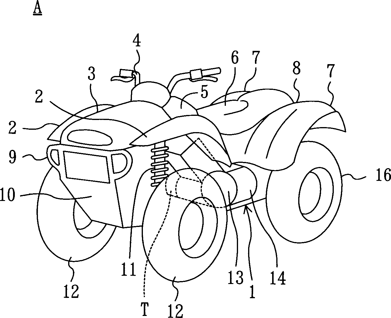
[0041] Embodiment 1 of the present invention will be described in detail below with reference to the accompanying drawings. This embodiment is a 4-wheel drive all-terrain vehicle (A) equipped with a hydromechanical transmission (HMT) (T) according to the present invention. figure 1 Indicates the appearance of the all-terrain vehicle (A), and the symbol (1) is a chassis with details omitted. On the top of this car body chassis (1), the front engine cover (3) that is provided with front left and right fenders (2), (2) is arranged from front to back, steering handle (4), fuel tank (5), Chair (driver's seat) (6), and rear engine cover (8) that is provided with rear left and right fenders (7), (7).

[0042] A lower engine cover (10) integrated with a bumper (9) is provided at the frontmost part of the car body below the above-mentioned front engine cover (3), and the front wheels connected by suspension front shock absorbers (11) are arranged on the left and right sides behind it....

Embodiment 2

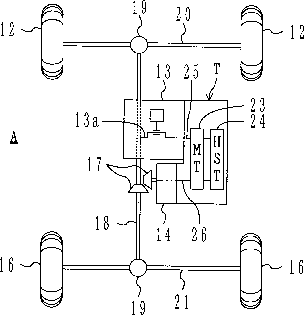
[0071] Figure 5 The structure of the power transmission system of the all-terrain vehicle (A) equipped with the hydromechanical transmission (T) concerning the 2nd Embodiment of this invention is shown. In this embodiment 2, the casing of the hydromechanical transmission (T) is divided into two parts, the hydrostatic transmission casing and the mechanical transmission casing. Except for this point, the hydromechanical transmission of embodiment 2 The structure of the device (T) is the same as that of the above-mentioned first embodiment, therefore, the same components are marked with the same symbols and descriptions are omitted. And, as shown in the figure, the casing of the hydromechanical transmission (T) in Embodiment 2 can be divided into a mechanical transmission casing (80) for accommodating a mechanical transmission (23) and a casing for accommodating a hydrostatic transmission. The hydrostatic transmission case (81) of the device (24), wherein the mechanical transmi...

Embodiment 3

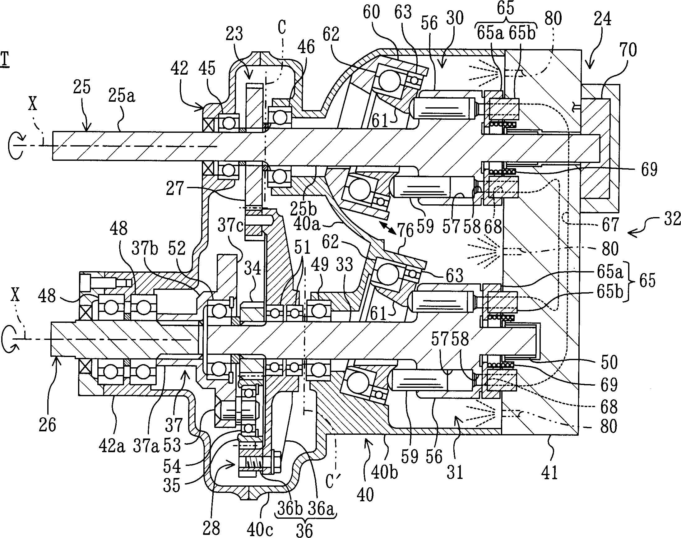
[0076] Figure 7 A hydromechanical transmission (T) according to Embodiment 3 of the present invention is shown. What this embodiment 3 describes is that, as the piston pump (30) and the motor (31) of the hydromechanical speed change device (T), the pump shaft part (25b) of the cylinder barrel (56) and the input shaft (25) , motor shaft (33) are separately made separately, intermesh by spline shaft. At the same time, the input gear (27) of the mechanical transmission (23) is integrally formed on the above-mentioned input shaft, and the sun gear (34) of the motor shaft (33) and the planetary gear mechanism (28) is integrally formed.

[0077] Also, above-mentioned piston pump (30) and motor (31), as above-mentioned each embodiment, replace floating type valve plate (65) and use general valve plate (90), use coil spring (92) to this shutter ( 90) is tightly pressed on the friction plate part (91) arranged on the back side of the end cover (41).

[0078] Have again, above-menti...


PUM


Abstract

An HMT apparatus (T) is mounted on a vehicle (A). In the HIVIT apparatus (T), input rotational force from an engine is once divided into two systems which are then transmitted by an MT device and by an HST device respectively and are resynthesized for transfer toward wheels. The HIVIT apparatus (T) is disposed on the vehicle-body right side of the engine which is sideways-mounted on a vehicle body, and its input and output shafts are disposed in parallel with a crank shaft of the engine and are disposed to run parallel with each other. The input shaft is coupled directly to the crank shaft and an input gear of the MT device is mounted on the input shaft, and a hydraulic piston pumpof the HST device is connected to the right side end of the input shaft. A planetary gear mechanism of the MT device is connected to the right side end of the output shaft, and a hydraulic piston motor of the HST device is connected to the right side of the planetary gear -mechanism. By virtue of such arrangement, it is possible to improve the degree of freedom of the layout of each component of the HMT apparatus (T), to reduce axial dimensions, and further to provide improvement in the cooling property and maintenance property of the section of the HST device.

Description

technical field [0001] The present invention relates to a hydro-mechanical transmission (Hydro-MechanicalTrans mission, referred to as HMT) composed of a hydrostatic transmission consisting of a variable-capacity piston pump / motor and a mechanical transmission, and the transmission installed vehicle. In particular, the propeller shaft (output / output) of the case where a speed change device is installed under the driver's seat of an All-Terrain Vehicle (ATV) such as a three-wheeled or four-wheeled vehicle (buggy), a tractor, or a motorcycle, etc. The technical field of the arrangement of the axis). technical background [0002] So far, as the transmission device of a four-wheeled vehicle, a continuously variable transmission by a belt drive mechanism has been included. However, when such a belt type continuously variable transmission is used, frequent maintenance is required under particularly severe operating conditions. Therefore, in recent years it is being replaced by a...

Claims


Application Information

Patent Timeline
Patent Type & Authority Applications(China)
IPC IPC(8): B60K17/04B60K5/04B60K17/10B60K17/34F16H47/04F16H57/02F16H57/023F16H57/037F16H57/038F16H57/039
CPCB60K17/34B60K17/10B60Y2200/124F16H47/04B60Y2200/12F16H2037/088B60K5/04
Inventor 谷信幸
Owner SAUER DANFOSS DAIKIN
Why Eureka
Try Eureka