New technological method-2 for detecting shear wave speed in geotechnical static and dynamic triaxial instrument

A dynamic three-axis, shear wave technology, applied in the direction of soil material testing, instruments, measuring devices, etc., can solve the problems of reducing shear wave energy, limiting the service life of devices, and not being able to use sensors

Inactive Publication Date: 2003-11-26
TIANJIN UNIV
View PDF0 Cites 7 Cited by
  • Summary
  • Abstract
  • Description
  • Claims
  • Application Information

AI Technical Summary

Problems solved by technology

This method has the following disadvantages: ①The bending unit needs to be inserted into the test piece to a certain depth (generally 3mm), which causes a certain disturbance within the range of the insertion depth, and also causes uncertainty in the propagation length of the shear wave. The error caused by the item can reach 16%; ②The near-field effect and the interference of stray waves make the first arrival of the shear wave more subjective, and the resulting measurement error can reach 30%; ③The bending unit A polarized wave is generated, and the sensitive directions of the transmitting and receiving units must be aligned in the same direction during the test to effectively receive the test signal; ④ Since the bending element needs to be inserted into the soil frequently, the insulation and waterproof problems are difficult to deal with, which also limits the service life of the device
This type of sensor has the following problems when measuring the shear wave velocity of soil samples indoors: ①Thickness shear is a high-frequency vibration mode (the vibration frequency of the chip used to make the thickness shear vibration mode of the sensor is usually greater than 400kHz), and the electromechanical The coupling coefficient is low, the radiation energy of the sensor is small, and the shear wave propagation distance is very short; ②The characteristic impedance of the PZT chip is much larger than that of the soil sample, which makes it difficult to match between the two, thereby further reducing the penetration into the soil. Shear wave energy; ③The longitudinal wave interference cannot be suppressed, especially for high-loss media such as clay and saturated loose sand, the longitudinal wave interference is very serious, which makes this method only suitable for testing the shear wave velocity of dry sand, and requires filtering Technology and certain vibration phase identification skills
Therefore, it is almost impossible to use such sensors in dynamic and static triaxial tests

Method used


Image

  • New technological method-2 for detecting shear wave speed in geotechnical static and dynamic triaxial instrument
  • New technological method-2 for detecting shear wave speed in geotechnical static and dynamic triaxial instrument
  • New technological method-2 for detecting shear wave speed in geotechnical static and dynamic triaxial instrument

Examples


Embodiment Construction

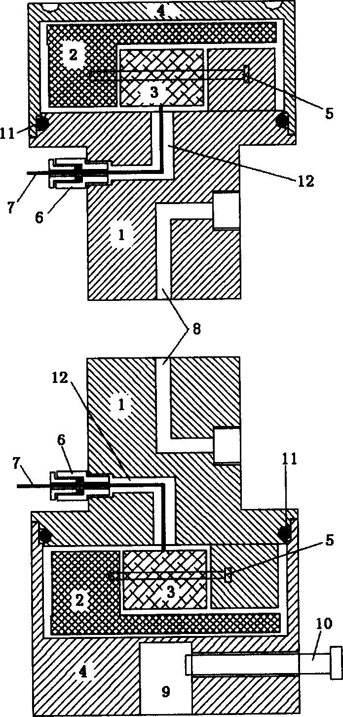
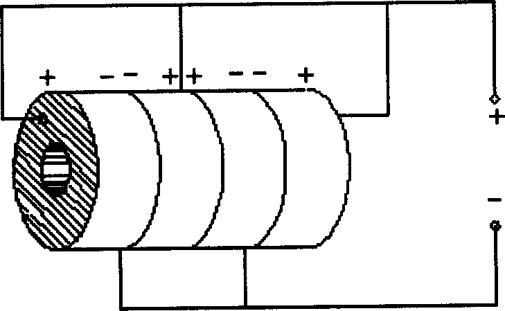
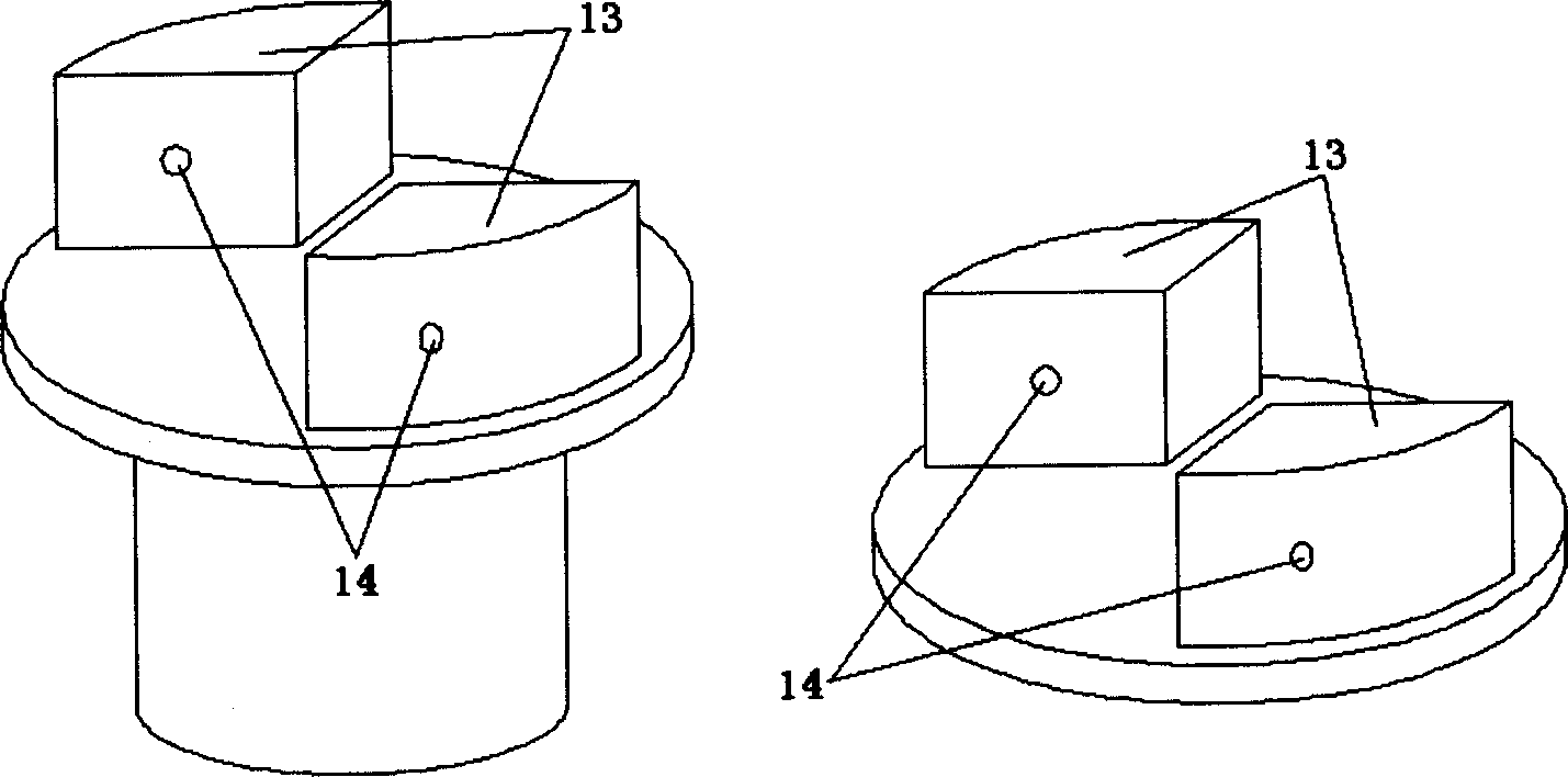
[0009] Refer to attached Figure 1~4 . Among them, the front cover (1) is made of light hard metal, the rear cover (2) is made of heavy metal such as stainless steel or copper, the diameter of the front and rear cover is φ39.1mm, the diameter of the shell (4) is φ70mm, the upper sensor The height is 50mm and the lower sensor is 70mm. First, the electrodes of the piezoelectric composite ceramic rod pair (3) are connected well, and the cable (7) protrudes from the cable outlet hole (12) to the outside of the front cover plate (1). Then use the assembly bolts (5) to pass through the pair of piezoelectric composite ceramic rods (3) and the bolt holes (14) of the fan-shaped cylinder to fix the front and rear cover plates together. An O-ring is put on the groove of the front cover (1), and the front cover, the rear cover and the piezoelectric composite ceramic rod are placed in the shell (4). Finally, the outgoing cable (7) is passed through the cable outgoing joint (6) and fixed...


PUM

PropertyMeasurementUnit
diameteraaaaaaaaaa
diameteraaaaaaaaaa
heightaaaaaaaaaa

Abstract

Front and back cover plates and a pair of composite piezoelectrical ceramic rods are fixed into one integral and set inside a casing to constitute the sensor and connected hermetically via O-ring andcasing. The front cover plate is one stepped cylinder with two fanned columns in the top, and the circular back cover plate has also two fanned columns in the diagonal line positions. Each of the composite piezoelectrical ceramic rods is constituted by several laminated PZT rings in parallel connection, and is sandwiched between the fanned columns of the front and the back cover plates. When twocomposite piezoelectrical ceramic rods stretch and withdraw simultaneously, one torque is formed in the front and the back cover plates to produce torsion vibration. The present invention has the advantages of low operation frequency, small volume and great radiation energy of the sensor, is suitable for shear wave speed in various soil sample, and can inhibit longitudinal wave interference and distinguish the first arrival time of shear wave.

Description

technical field [0001] The invention relates to a geotechnical engineering testing technology. Background technique [0002] In geotechnical engineering, the shear wave velocity of the soil layer is an important soil parameter, which has been highly valued and widely used. At present, the bending element method is commonly used in geotechnical static and dynamic triaxial instruments to test the shear wave velocity. This method has the following disadvantages: ①The bending unit needs to be inserted into the test piece to a certain depth (generally 3mm), which causes a certain disturbance within the range of the insertion depth, and also causes uncertainty in the propagation length of the shear wave. The error caused by the item can reach 16%; ②The near-field effect and the interference of stray waves make the first arrival of the shear wave more subjective, and the resulting measurement error can reach 30%; ③The bending unit A polarized wave is...

Claims


Application Information

Patent Timeline
Patent Type & Authority Applications(China)
IPC IPC(8): G01N33/24
Inventor 王建华程国勇张立
Owner TIANJIN UNIV
Why Eureka
Try Eureka