Inflatable support pad

A technology of air pressure and air chamber, applied in the field of inflatable air pressure cushion device

Inactive Publication Date: 2003-11-26
KCI LICENSING INC
View PDF0 Cites 11 Cited by
  • Summary
  • Abstract
  • Description
  • Claims
  • Application Information

AI Technical Summary

Problems solved by technology

This system has the same problem as above

Method used


Image

  • Inflatable support pad
  • Inflatable support pad
  • Inflatable support pad

Examples


Embodiment Construction

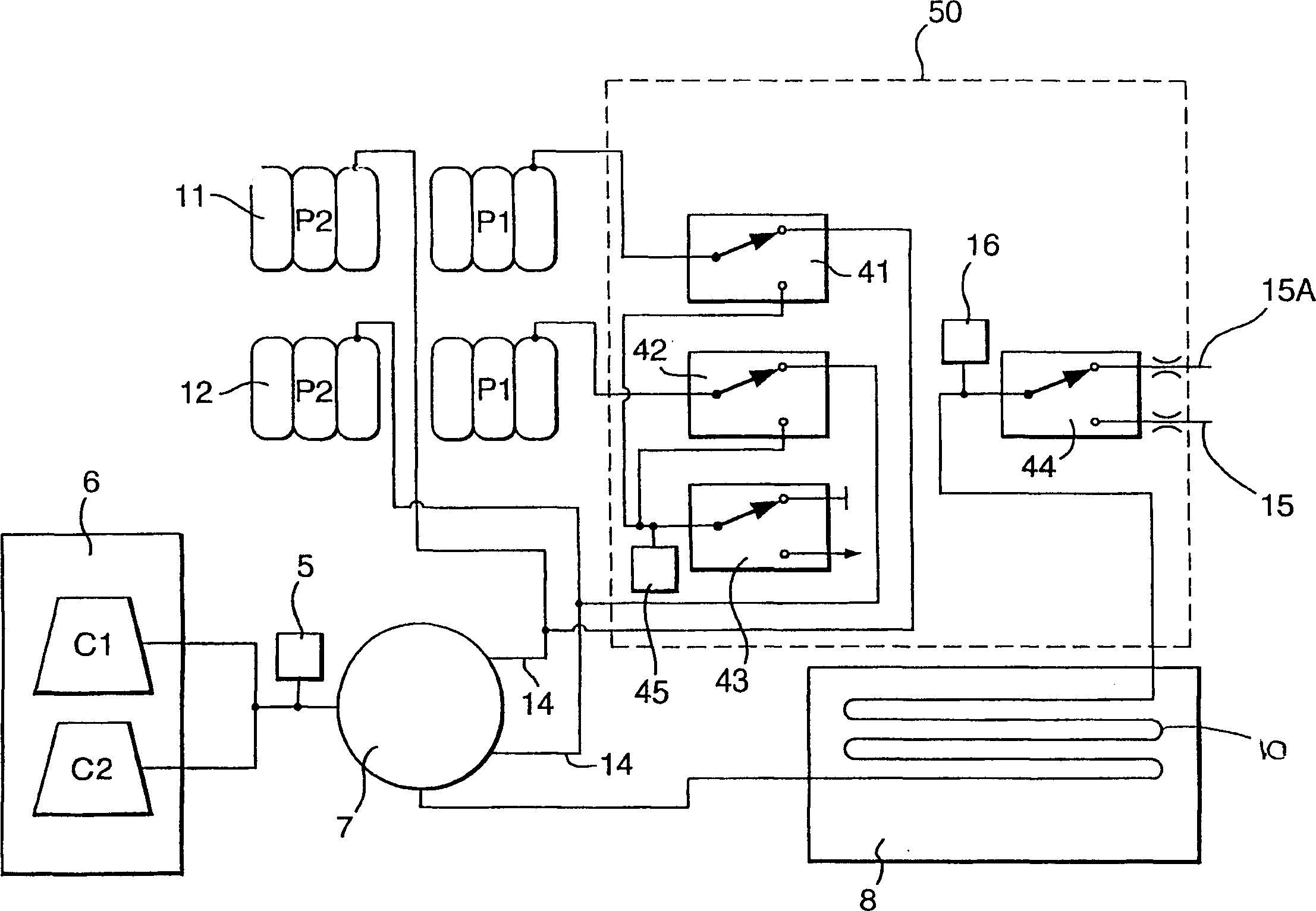
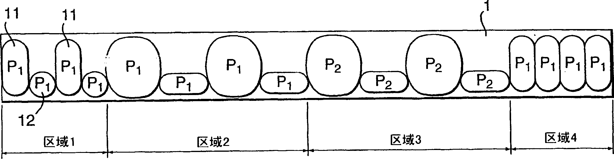
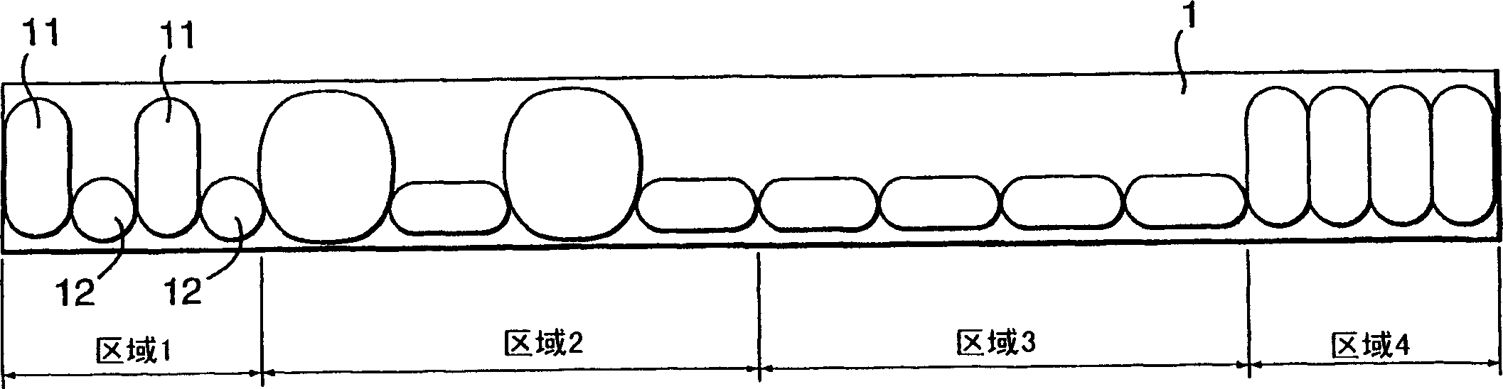
[0024] refer to figure 1 , The alternating air pressure cushion 1 includes the first group 11 and the second group 12 of air chambers that can be inflated alternately. Gas is delivered from the air pump 6 through the rotatable valve 7 to two groups of inflatable air chambers, and a pair of air supply pipes 14 lead to the air cushion from the rotatable valve.

[0025] The tubing 10 in the sensing pad 8 is connected at one end to the output of the air pump 6 and at the other end to the solenoid 44, the pressure sensor 16 and the two different restrictors 15 and 15a. A part of the pipeline 10 is under the air cushion 1 to receive the pressure exerted by the patient, and can be compressed according to the magnitude of the applied pressure.

[0026] In this embodiment, the compressible part of the pipe 10 is a single compressible pipe designed as a coiled channel and forms an induction pad 8 . The air cushion can be formed by joining two polyurethane (polyurethane) sheets, in whi...


PUM


Abstract

A pressure pad (1) has two sets of cells (11, 12) with a sensor pad (8) positioned under the pad (1). During inflation, part of the low goes to the sensor pad (8) to exhaust and the rest fills the cells (11 or 12). Any change in patient position / weight causing a change in airflow in tube (10) will alter the differential pressure measured at the pressure transducer (16). Based on this feedback the microprocessor directly controls the power level to the pump (6) thus adjusting the airflow to the cells to prevent bottoming or to rung at a minimum pressure. The pressure pad (1) is segmented into a heel section, upper leg section, torso section, and a head section. The heel, head and upper leg sections are maintained at a lower pressure P1 and the torso section at a higher pressure P2. A control module (50) to control the flow in the segments is provided inside the pressure pad (1). The pressure pad (1) can be an alternating or static pad.

Description

technical field [0001] The invention relates to an inflatable air cushion device controlled by pressure, in particular to an alternating or static inflatable air cushion device with controllable pressure. Background technique [0002] The use of alternating air pressure cushions for the prevention and treatment of supine ulcers in bedridden patients is known. Lying ulcers, commonly known as decubitus ulcers, develop due to a number of factors, one of which is the pressure exerted on an area of ​​the bedridden patient's skin. [0003] Alternating air cushions generally include two sets of alternating inflatable chambers. The duration of the inflation and deflation cycle may be less than two minutes. Creates a gentle massage that can last up to twenty minutes or more. [0004] In the air cushion, high air pressure can be used to support the patient's bone protuberance to ensure that the patient is effectively supported, leaving the deflated air chamber in the air cushion to...

Claims


Application Information

Patent Timeline
Patent Type & Authority Applications(China)
IPC IPC(8): A47C27/10A61G7/05A61G7/057A61H7/00F04B49/06
CPCA61G7/05776
Inventor 保罗·威廉·查普曼简·哈比格丹尼尔·肯普安东尼·乔治·史密斯
Owner KCI LICENSING INC
Why Eureka
Try Eureka