Melting and spinning device and melting and spinning method

A technology for melting spinnerets and nozzles, which is applied in the field of medical materials, and can solve the problems of inability to uniformly decompose and absorb the entire graft fixer, inability to support vessels such as blood vessels, and uneven strength.

Inactive Publication Date: 2003-12-10
IGAKI IRYO SEKKEI
View PDF1 Cites 4 Cited by
  • Summary
  • Abstract
  • Description
  • Claims
  • Application Information

AI Technical Summary

Problems solved by technology

[0012] When a stent is implanted in a blood vessel such as a blood vessel using such a silk with a non-uniform average molecular weight, the whole stent cannot be uniformly decomposed and absorbed.
In addition, stents using such silk cannot support the inner walls of blood vessels such as blood vessels with uniform force because the strength of the silk itself is not uniform.

Method used


Image

  • Melting and spinning device and melting and spinning method
  • Melting and spinning device and melting and spinning method
  • Melting and spinning device and melting and spinning method

Examples


Embodiment Construction

[0029] The melt-spinning device of the present invention and the method of melt-spinning a biodegradable polymer material using the melt-spinning device will be described in more detail below.

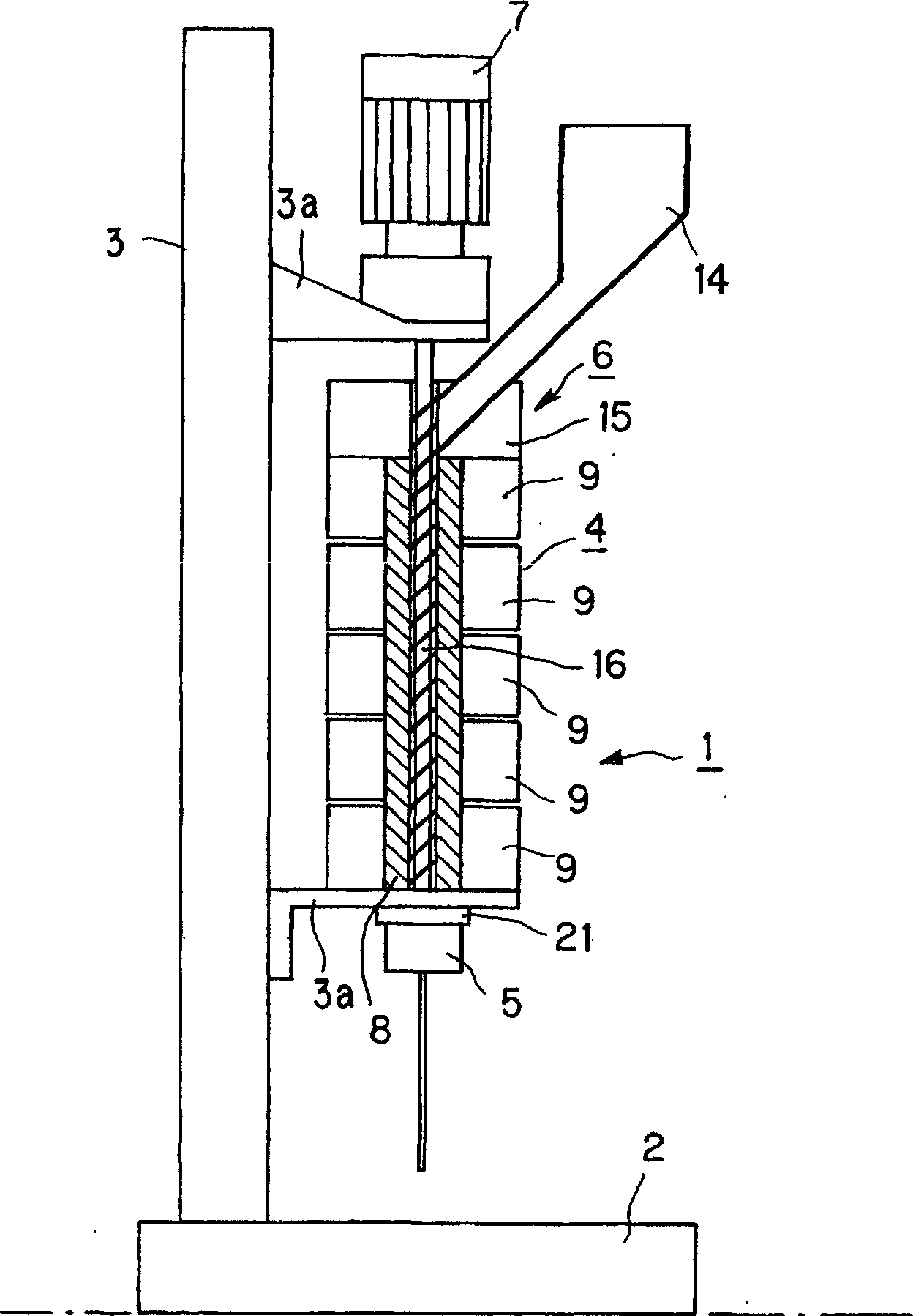
[0030] Melt spinning device of the present invention, such as figure 1 Shown is a vertical melt-spinning device in which the melt-spinner is installed vertically.

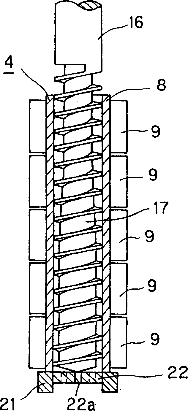
[0031] figure 1 The melt-spinning apparatus shown has a substrate 2 installed horizontally on an installation surface, and a melt-spinner 1 supported by a support member 3 a on a support 3 vertically installed on the above-mentioned substrate 2 . The melt spinning machine 1 is equipped with: a melting mechanism 4 supported in parallel on the vertically arranged pillar 3, a discharge part 5 for ejecting the polymer material melted by the melting mechanism 4, and a supply of the polymer material to the melting mechanism 4. Part 6, and a rotary drive mechanism 7 that rotationally drives the screw 16 constituting the melting ...


PUM


Abstract

The present invention is relative to a melt spinning apparatus for melt spinning a biodegradable polymer material. The biodegradable polymer material is melted by a melt mechanism (4) including a screw (16) which is mounted in a vertically mounted cylinder (8) coaxially with the cylinder (8) and which is rotationally driven by a rotational driving mechanism (7). The screw includes at least one turn of a helical groove (17) on its peripheral surface. The biodegradable polymer material being melted in this way is discharged in the vertical direction from a discharge opening of a nozzle (10) mounted coaxially on the cylinder (8).

Description

technical field [0001] The present invention relates to a melt-spraying device and a melt-spraying device for melt-spraying filaments made of a medical material for implantation into a living body, such as a biodegradable polymer material forming a stent implanted in a blood vessel of a living body. Spinning method. Background technique [0002] Conventionally, when a stenosis occurs in a blood vessel of a living body, especially a blood vessel such as an artery, a balloon attached near the tip of a catheter is inserted into the stenosis, and the stenosis is expanded by expanding the balloon, thereby performing an operation to ensure blood flow. percutaneous transluminal angioplasty (PTA). [0003] However, it is well known that even after percutaneous angioplasty, there is a high probability of reoccurrence of stenosis at the site where stenosis occurred. [0004] In order to prevent restenosis, a tubular stent is reimplanted in the part where percutaneous angioplasty has...

Claims


Application Information

Patent Timeline
Patent Type & Authority Applications(China)
IPC IPC(8): D01D1/04D01D1/06D01D5/08D01F6/62
CPCD01D1/04D01D1/06D01D5/08
Inventor 伊垣敬二山根秀树
Owner IGAKI IRYO SEKKEI
Why Eureka
Try Eureka