Gripping implement with improved arrangement

A technology for improving structures and tools, applied in the field of holding tools, can solve problems such as troublesome identification, sticking, and inconvenient use, and achieves the effects of cost-effectiveness, simple structure and low cost

Inactive Publication Date: 2003-12-31
谢智庆
View PDF0 Cites 2 Cited by
  • Summary
  • Abstract
  • Description
  • Claims
  • Application Information

AI Technical Summary

Problems solved by technology

[0002] The current general holding tool has such as figure 1 The structure of the generally common grip shown is that the grip is mostly a smooth surface, and the smooth surface generally does not cause too much influence during use, but it will be affected by the user during operation. Sweat or machine oil stains stick to the grip part, causing the user to accidentally fall out and slip when applying force
[0003] Furthermore, there are many kinds of holding tools at present, among which, such as ratchet wrenches, ring wrenches, and double-ended wrenches of different sizes, all have their own purposes of use. Therefore, when ordinary people use holding tools, in order to apply to various In other cases, it is necessary to observe the marking structure visually in order to achieve the purpose of changing sides or reverse use, which will cause great inconvenience in use, and its defects are described in detail as follows:
[0004] Ordinary wrenches have their direction in use, and the existing wrenches are all of the same smooth surface structure, so they cannot be easily identified when they are held, which will cause great trouble in use , for example, taking the most common car maintenance as an example, when the user puts the tool body into the bottom of the car (that is, the situation where the tool body cannot be seen), if the tool body may need to be replaced during use Orientation, but to change another size or structure, most people take it out for viewing and then turn it around, which is extremely impractical. The main reason is that a single wrench has four states with different directions and sizes. , so it is extremely impractical to operate;
[0005] Furthermore, in terms of the usability of the size of the same end, the general wrench has an angle, which is intended to make use of the angle during the rotation process, and when used in a narrow space, there is still room for rotation, and also That is to say, when it is constantly rotating, it is necessary to take out the wrench at intervals of a short period, and then rotate it in the opposite direction, so that it can be used alternately to achieve the effect of completely screwing it out. Appearance, it will definitely cause confusion to the user in use, and the size needs to be observed visually before it can be used again. This kind of conventional smooth surface is not only prone to slipping and falling out during use. Disadvantages, but also cause considerable trouble in the use of identification, so on the whole, it is quite impractical

Method used


Image

  • Gripping implement with improved arrangement
  • Gripping implement with improved arrangement
  • Gripping implement with improved arrangement

Examples


Embodiment Construction

[0022] Below, with reference to the accompanying drawings and preferred embodiments, the specific implementation, structure, features and functions of the gripping portion with improved structure proposed according to the present invention will be described in detail as follows.

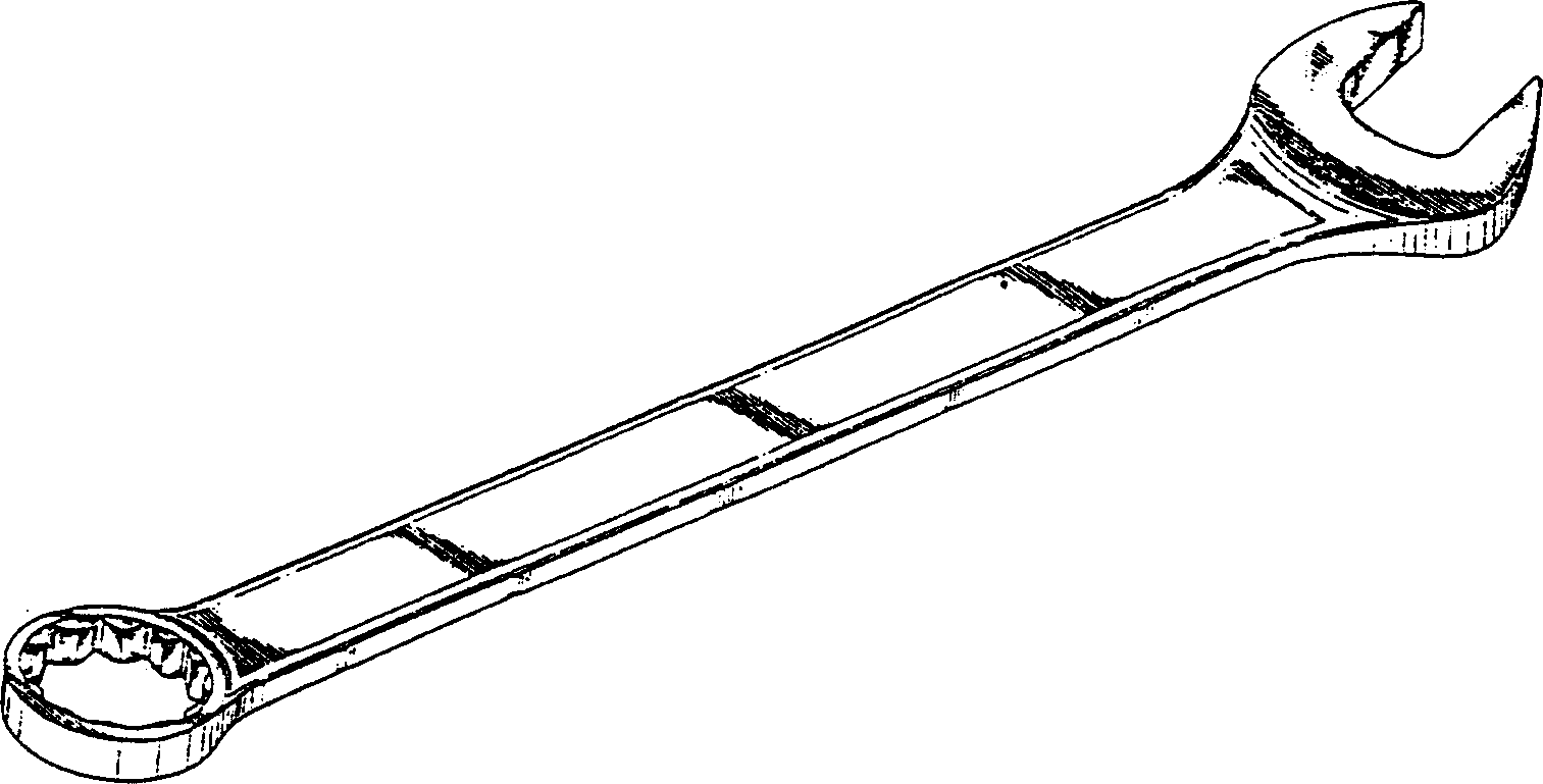
[0023] figure 1 In the existing conventional grip structure shown, the grip tool body 1 is smooth.

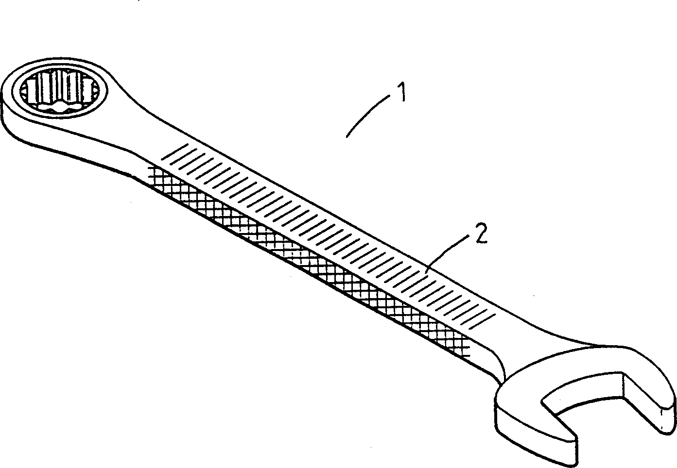
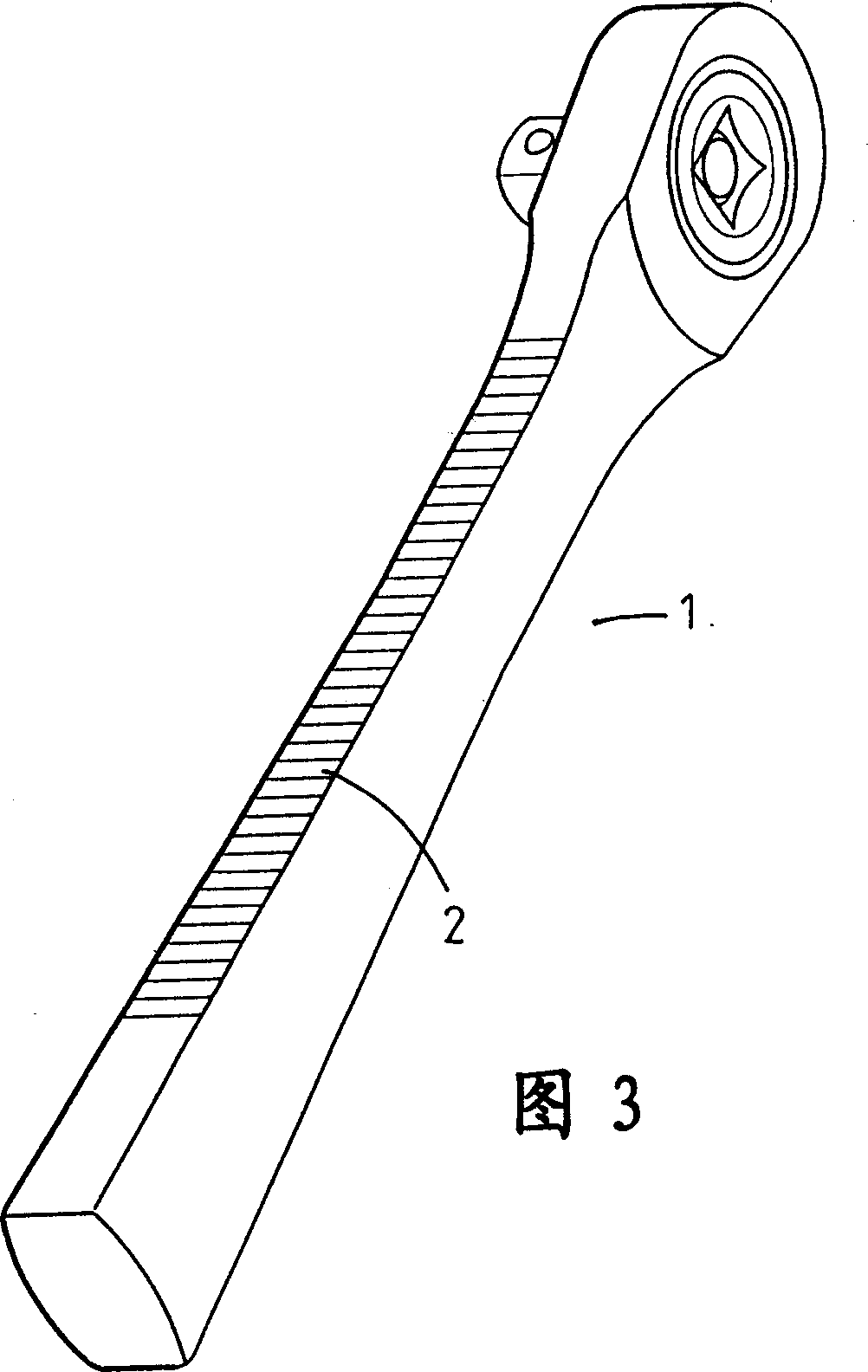
[0024] Figure 3 and Figure 7 to Figure 13 As shown, the holding tool with improved structure of the present invention mainly includes a holding tool body 1 , and an embossed portion 2 is formed on at least one side of the holding tool body 1 . The embossed portion 2 can be straight grain, twill grain, cross grain or a combination of straight grain and cross grain.

[0025] Such as figure 2 As shown in FIG. 4 to FIG. 6 , the holding tool with improved structure of the present invention mainly includes a holding tool body 1 , and embossed parts 2 are formed on both sides of the holding tool body 1 ...


PUM


Abstract

The hand-held tool in improved structure has one main body, which has knurled part formed in at least one edge for both antiskid and distinction. The present invention has industrial application value.

Description

technical field [0001] The invention relates to a holding tool, in particular to a holding tool with an improved structure. It uses the same or different embossed parts at different positions to achieve the functions of anti-slip and easy identification. Background technique [0002] The current general holding tool has such as figure 1 The structure of the generally common grip shown is that the grip is mostly a smooth surface, and the smooth surface generally does not cause too much influence during use, but it will be affected by the user during operation. Sweat or machine oil stains stick to the grip, causing the user to accidentally fall out and slip when applying force. [0003] Furthermore, there are many kinds of holding tools at present, among which, such as ratchet wrenches, ring wrenches, and double-ended wrenches of different sizes, all have their own purposes of use. Therefore, when ordinary people use holding tools, in order to apply to various In other case...

Claims


Application Information

Patent Timeline
Patent Type & Authority Applications(China)
IPC IPC(8): B25B13/00B25B23/16
Inventor 谢智庆
Owner 谢智庆
Why Eureka
Try Eureka