Expansion joint regulator element and expansion joint regulator made therefrom

A regulator and expansion joint technology, applied in bridge parts, bridges, buildings, etc., can solve problems such as unfavorable popularization and application, complex structure, and large maintenance volume, and achieve the effect of facilitating popularization and application, improving mechanical properties, and reducing self-weight load.

Inactive Publication Date: 2003-12-31
李永政
View PDF1 Cites 14 Cited by
  • Summary
  • Abstract
  • Description
  • Claims
  • Application Information

AI Technical Summary

Problems solved by technology

This technical solution achieves the effects of driving stability and flexible expansion and contraction, but this technical solution requires metal processing and is constructed by welding. The integrity is poor, the structure is complicated, the manufacturing of cables is complicated, it is prone to failure, and the amount of maintenance is large, which is not conducive to Promote application

Method used


Image

  • Expansion joint regulator element and expansion joint regulator made therefrom
  • Expansion joint regulator element and expansion joint regulator made therefrom
  • Expansion joint regulator element and expansion joint regulator made therefrom

Examples


Embodiment 1

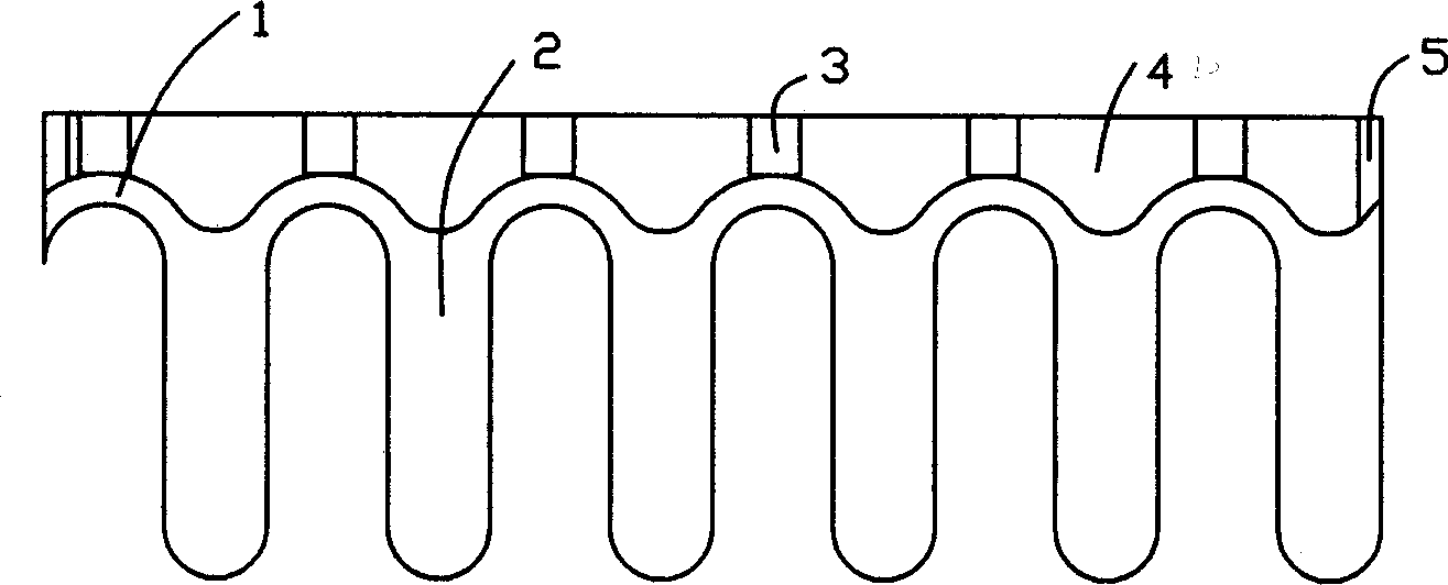
[0025] Such as figure 1 The shown expansion joint adjuster component is composed of a telescopic back 1 and a telescopic beam 2 that is equidistant from one side of the telescopic back 1 and is uniformly casted. The telescopic beams are equal in length, parallel to each other, and perpendicular to the telescopic back. The top and bottom planes of the telescopic back 1 coincide with the top and bottom planes of the telescopic beams 2. The cross-section of each telescopic beam is an "I"-shaped structure with the same width at the bottom and top, such as Figure 5 shown. The width of each telescopic beam is smaller than the distance between each other. On the outer back of the telescopic back, there are evenly fixed threaded joints 3 for connecting the embedded connecting rods. In order to facilitate the fixed connection of two adjacent components, the two ends of each component are provided with fixing ears 5 with bolt holes 8. Such as Figure 4 As shown, at the same time, i...

Embodiment 2

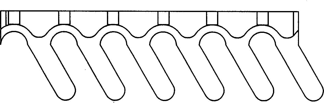
[0027] Such as figure 2 As shown, the basic structure of this embodiment is the same as that of Embodiment 1, the difference is that in order to meet some specific requirements for use, the stretching direction of the telescopic beam is deflected to the right to form an angle less than 90° with the telescopic back , which is set to 30° in this embodiment.

Embodiment 3

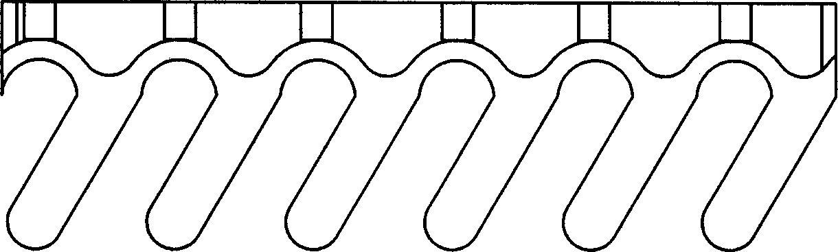
[0029] Such as image 3 As shown, its basic structure is still the same as that of Embodiment 1. For the same consideration as Embodiment 2, in order to meet some specific requirements for use, the stretching direction of the telescopic beam is deflected to the left and the telescopic back forms a less than 90 ° angle. In this embodiment, it is set to 30°.


PUM


Abstract

The expansion joint regulator member consists of expansion back and cast expansion beams on sides of the expansion back. The expansion beams are equal in length and parallel, and the expansion back has its top and bottom planes coinciding with the top and bottom planes of the expansion beams. The expansion joint regulator consists of two identical members inserted mutually. The member is formed through once casting. The expansion joint regulator with two identical members inserted mutually can avoid resonance caused by the impact of the running vehicles, and prolong the service life of bridge and other buildings.

Description

technical field [0001] The invention relates to an expansion joint adjuster component used on buildings such as bridges and the expansion joint adjuster formed therefrom. Background technique [0002] Expansion joint regulators are used in many buildings. For bridges, the role of expansion joint regulators is more obvious. The expansion joint adjuster can eliminate the gap at the bridge joint and eliminate the impact caused by the jump when the vehicle passes, which is helpful for smooth driving and prolonging the service life of the bridge. [0003] The "China Utility Model Patent Bulletin" announced a utility model patent with the patent number ZL93219115 and the name "Interactive Socket Type Bridge Expansion Joint". Between the two support boxes, there are telescopic beams arranged on the partition board. The opposite ends of two adjacent telescopic beams are fixed on the transverse partition plate of the support box, and the other opposite ends are equipped with rollers...

Claims


Application Information

Patent Timeline
Patent Type & Authority Applications(China)
IPC IPC(8): E01D19/06
Inventor 李永政鲁书林陈大根李西梅
Owner 李永政
Why Eureka
Try Eureka