
Water solution system local corrosion speed online electrochemistrical monitoring probe

A localized corrosion and chemical monitoring technology, applied in the direction of measuring devices, instruments, mechanical devices, etc., can solve problems such as difficulty in determining corrosion, costing more time and cost, and inability to measure localized corrosion

Inactive Publication Date: 2003-12-31
INST OF METAL RESEARCH - CHINESE ACAD OF SCI
View PDF0 Cites 3 Cited by
  • Summary
  • Abstract
  • Description
  • Claims
  • Application Information

AI Technical Summary

Problems solved by technology

Appropriate methods for evaluating equipment corrosion in industrial water systems include coupon weight loss method, linear polarization method, electrical resistance method, and observation and failure analysis. corrosion pit depth and other information, but these methods often need to spend more time and cost
In addition, the data obtained by these methods is the average corrosion rate for a period of time such as months or years. The actual corrosion rate is often affected by environmental factors such as temperature, medium flow rate, chemical composition of the medium, corrosion inhibitor additives, and pH value. , and in the industrial system, these environmental factors are always changing, so it is difficult to determine the real factor causing corrosion by using these methods
On the other hand, the polarization impedance technique and the electrical resistance method measure the average corrosion rate of the entire probe surface and cannot be used for localized corrosion measurements
Other techniques such as pitting index, electrochemical noise, and scanning reference electrode are also commonly used to study local corrosion, but due to their own characteristics, they cannot be used under normal conditions. Accurately obtain quantitative local corrosion rate
In short, so far, there is no mature on-site non-destructive testing technology for local corrosion speed at home and abroad, and it is impossible to effectively predict the risk of local corrosion.

Method used

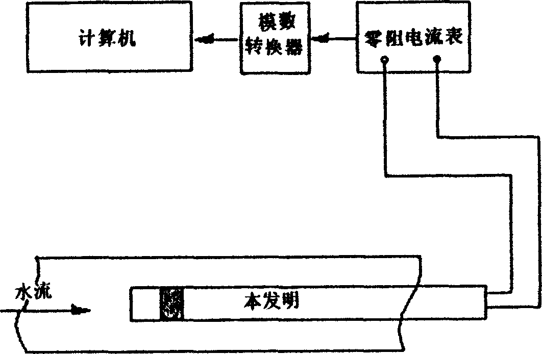
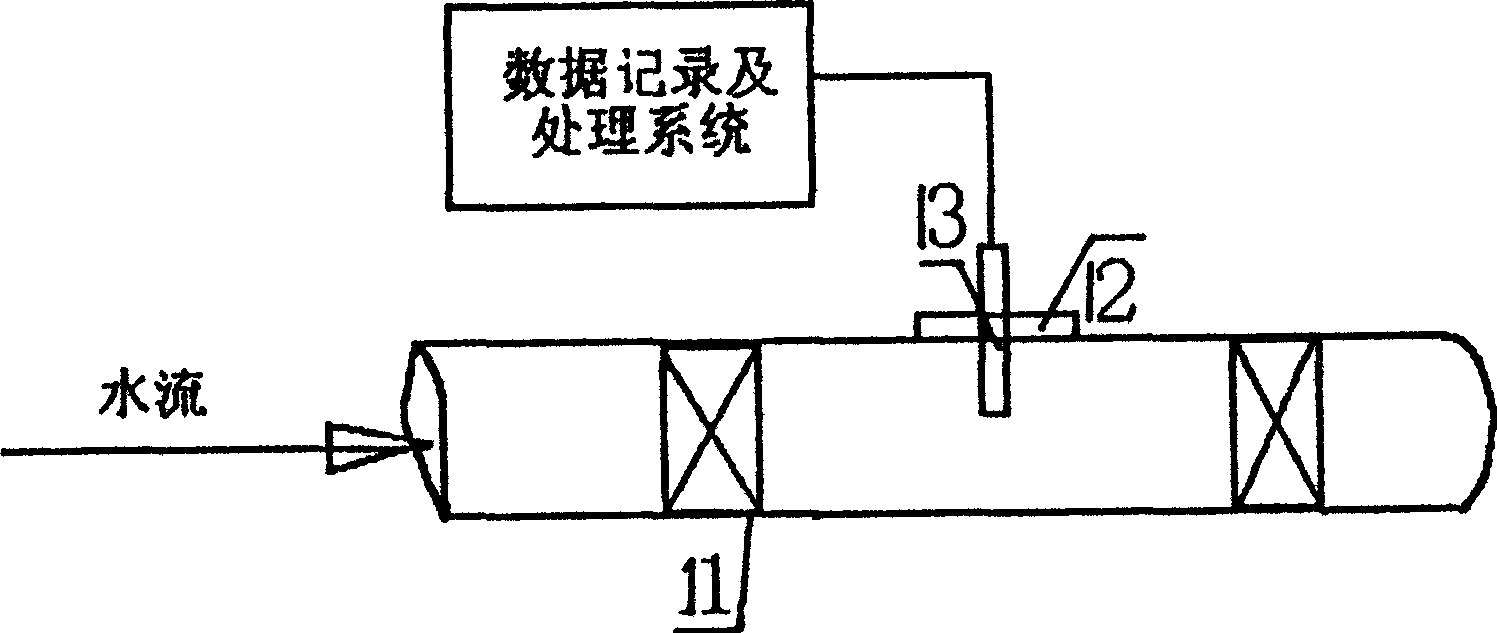

Image

  • Water solution system local corrosion speed online electrochemistrical monitoring probe
  • Water solution system local corrosion speed online electrochemistrical monitoring probe
  • Water solution system local corrosion speed online electrochemistrical monitoring probe

Examples


Embodiment 1

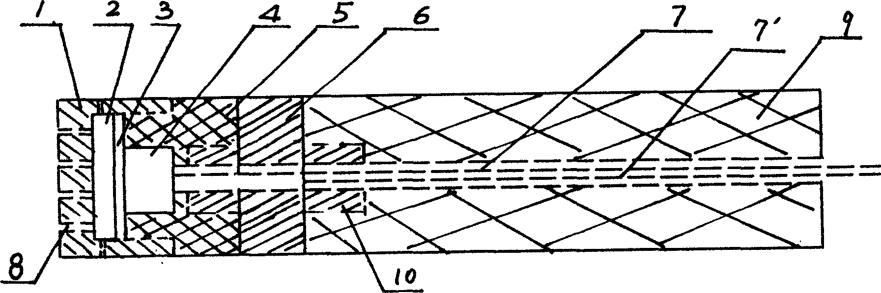
[0013] Such as figure 1 As shown, the present invention is a two-electrode system structure, which is mainly composed of a sheath 1, a filter membrane 2, a closed anode area 3, an anode 4, a sealing joint 5, a cathode 6 and a tail sleeve 9, wherein:

[0014] The front cover 1 is crown-shaped, and the inner end wall is provided with a filter membrane 2, and the sealing joint 5 accommodates the anode 4 in a groove thereof, and is connected with the inner side wall of the front cover 1 by a screw thread, and the filter membrane 2 is connected to the inner wall of the front cover 1. A blocked anode region 3 is formed between the surfaces of the anode 4;

[0015] The cathode 6 is a cylinder whose outer surface is an effective cathode surface area in contact with the bulk electrolyte. The two ends of the cathode 6 are provided with a thinner cylinder 10 with threads, and one end is connected to another groove of the sealing joint 5 The inner wall is tightly matched with threads, an...

Embodiment 2

[0028] It is used to measure the local corrosion rate of seawater, and the probe can be directly placed in the area to be measured for measurement. In this embodiment, the surface area of ​​the outer surface of the cathode 6 is 10 times that of the anode.


PUM


Abstract

The present invention relates to metal corrosion protecting technology, and is especially in-situ electrochemical monitoring probe for local corrosion rate in water solution system. The electrochemical monitoring probe is a two-electrode system comprising front cap, filtering film, closed anode area, anode, sealed joint, cathode and tail tube. The anode is held inside a notch in the sealed joint and the anode area is formed between the filtering film and the surface of the anode. The cathode is one cylinder with relatively small ends and has one effective cathode surface area on the surface. The anode and the cathode are connected via wires to outer measuring instrument. The front cap end and side wall have small hole canals communicated with the filtering film. The present invention is suitable for monitoring and detection of local corrosion rate in water solution system.

Description

technical field [0001] The invention relates to anticorrosion technology, in particular to an on-line electrochemical monitoring probe for local corrosion speed of aqueous solution system. Background technique [0002] In the prior art, methods to control localized corrosion failure usually include correct selection and use of high-standard materials, optimization of production process flow to improve equipment use environment, and reasonable use of corrosion inhibitors. The latter two methods require reliable methods for real-time monitoring of localized corrosion rates. Appropriate methods for evaluating equipment corrosion in industrial water systems include coupon weight loss method, linear polarization method, electrical resistance method, and observation and failure analysis. However, these methods often require more time and cost. In addition, the data obtained by these methods is the average corrosion rate for a period of time such as months or years. The actual co...

Claims


Application Information

Patent Timeline
Patent Type & Authority Applications(China)
IPC IPC(8): G01N19/02G01N19/04
Inventor 杜元龙雷良才阎一功
Owner INST OF METAL RESEARCH - CHINESE ACAD OF SCI
Learn More